Generally temperature changes will result in a change in a loadcell’s physical dimensions, shift in the zero balance of the bridge and a small change in the Young’s modulus or stiffness of the structure of the loadcell causing an output span change. Expansion of the loadcell body is compensated for by the bridge circuit used for the strain gauges. If the loadcell is constrained by an external structure a real load change may occur due to differential expansion. The changes in dimensions are the same for all the gauges so no output change occurs. This leaves just the latter two effects causing zero and span drift.
Zero drift is the change in zero load output of the loadcell, expressed as a percentage of the rated load output per °C. Once a production loadcell is stabilised we measure its zero drift in an environmental chamber. A small amount of temperature sensitive resistance wire is then added to the appropriate arm of the bridge circuit to compensate for the drift. The zero drift is then checked to ensure that the loadcell’s drift performance meets the required specification. On high specification loadcells some further fine tuning of the compensation may be required to achieve the required performance.
Zero drift is caused by a combination of factors associated with the components forming the bridge circuit. Variations in temperature distribution over the loadcell body can cause a zero drift greater than the data-sheet specification, a situation to be avoided if possible.
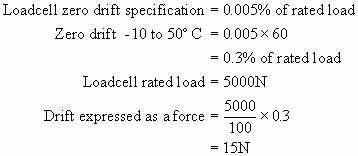
The error due to zero drift can be large in an application where there are large temperature changes. The error for a typical loadcell is shown in the example below. This error, expressed as a force, is independent of applied load so its effect is worse when forces that are only a small percentage of the rated load need to be measured. The zero error can be removed if a zero load output reading can be taken at the same operating temperature as the required load output reading. The actual load is then the difference between the two readings.

Span drift is the change in the output for an applied load, expressed as a percentage of the applied load output per °C. The loadcell body can be considered as a spring with a stiffness defined by Young’s modulus for the spring material. Young’s modulus decreases with rising temperature causing an increase in the loadcell output for an applied load. For standard temperature range loadcells we apply some compensation for this change by using proprietary nickel or balco modulus compensation resistors in series with the loadcell excitation supply. The resistance of these devices increases with rising temperature reducing the excitation supply to the bridge circuit which reduces the loadcell output for an applied load. Unfortunately the span drift of the loadcell and the temperature characteristics of the resistors are both non-linear so the resulting compensation is not perfect. The results are good over a range of -10°C to 50°C. The average span drift over this range of temperatures is quoted on the our loadcell data-sheets, expressed as a percentage of the applied load output per °C.
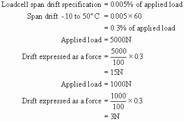
The error due to span drift can be large in an application where there are large temperature changes. The error for a typical loadcell is shown in the example below. This error, expressed as a force, is dependant on the applied load so its effect remains the same when forces that are only a small percentage of the rated load need to be measured.. If an application only requires load measurements at a relatively static high temperature the span drift error can be reduced by calibrating the loadcell at the nominal temperature.

The standard method for compensating for span drift error using nickel or balco foil resistors is limited in accuracy by the non-linear resistance change of the foil resistors with temperature. This non-linearity increases at temperatures above 100°C.
The standard foil resistors are not suitable for use at temperatures above 200°C. Novatech Measurements has developed a unique patented passive compensation method that produces accurate span drift compensation for force measurement loadcells at temperatures up to at least 250°C. Typical average span drifts of 0.005% of applied load per °C are possible from 0 to 250°C. If measurements are only required over part of this temperature range the average span drift can be improved. Values of 0.001% of applied load per °C have been achieved.
If you have an application where the temperature performance of a standard loadcell is not good enough our engineering department will advise you on the best solution.
