The F320 is based upon a common binocular beam structure, with eight strain gauges configured to provide a high degree of off axis compensation and moment rejection. Gauged in this manner, a binocular beam loadcell will result in very small errors, even for relatively large changes in the force application point. The Cantilever Bracket loadcell makes full use of this characteristic and is specifically intended for applications involving large moments/moment arms as part of the system design, rather than simply compensating for typical misalignment. The product data-sheet gives an outline that is universal across a wide range of loads, based on a sensible maximum moment arm. Standard F320 loadcells are designed to withstand full Rated Load at 500mm full cantilever. The data-sheet performance specification is based on this worst case moment arm position, although our standard calibration is carried out at a minimal moment arm unless otherwise requested.
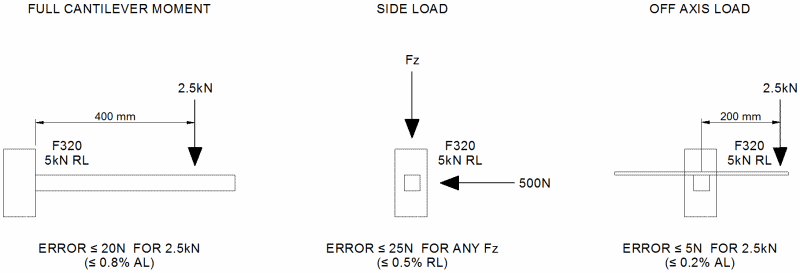
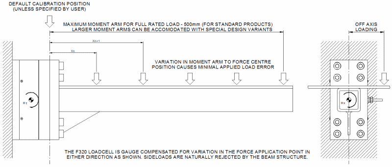
It is highly advisable to contact our engineering department when considering a Cantilever Bracket loadcell as the F320 is heavily application driven. We are able to offer both special design variants and calibration options depending on your requirements. It is important, for example, that we are aware of not only the force to be measured, but also the range of moment arms at which any given load may be applied. This may well affect our calibration procedures, such as the default calibration position. A couple of typical applications are detailed below.

In both cases above, the optimum calibration point is not the loadcell face, as would be our standard practice. By calibrating mid-range of the expected deviation in moment arms, the total error for an individual point can be greatly reduced. With the wave tank application in particular, the variation in moment arm is very little. However, the moment arm even at its shortest is very large. The error from a calibration done at the loadcell face compared to the midpoint of the minimum and maximum moment arm would be significant.
Although the standard design is based around a maximum moment arm, it is in fact the induced moment itself that is the limiting factor on the loadcell capacity. Therefore, proportionally less load could just as easily be applied at a larger moment arm without damage to the sensor. In this case however, the error may be a greater percentage of the applied load. The robotic arm, as an example, could pick up a smaller weight at a greater distance but the accuracy may be slightly reduced.
Error Evaluation
Error evaluation during product development was conducted in accordance to a strict methodology. Prototype loadcells were calibrated to our usual high standards to obtain control data, before being subjected to their full moment capacity in 12 stages in order to fully characterise their behaviour. The data for varying applied loads at varying moment arms was tabulated and manipulated using straight line maths. The following graphs are for a 5kN loadcell under cantilever moment testing.
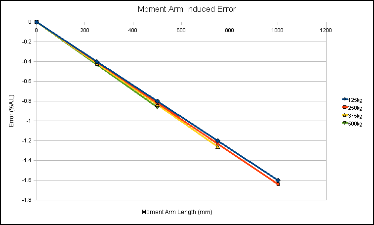
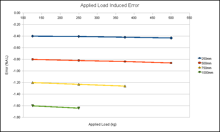
F320 5kN Prototype Results for Applied Load and Moment Arm Induced Errors
The moment arm error graph (top), plots applied load error against increasing moment arm lengths for a selection of applied loads. It can be seen that the change in applied load has very little effect as all of the four lines are almost perfectly superimposed. The applied load error graph (right), shows more clearly the dominance of the effect of increasing moment arm length. Both graphs show that the error as a percentage of the applied load is linearly related to the length of the moment arm, whereas the the effects of a change in applied load at a fixed moment arm and increasing moments themselves are insignificant. The same nature of results was found for off axis loads up to 250mm either side of the moment arm centreline. The following are typical across all data-sheet ranges:

Put into words, we can expect no more than 1%AL error for any applied load at any cantilever moment arm length within the designed 500mm. We can also expect no more than 0.25%AL error for any applied load at any distance offset from the moment arm centreline within ±250mm. These errors are independent and the two should therefore be combined where both situations are present. This gives a maximum 1.25%AL error for a load positioned anywhere within the planar 500mm square loading envelope as mentioned earlier.
The fact that the moment arm length is more influential than the magnitude of the moment itself, suggests that the majority of the error is due to the stiffness of the moment arm used in our rig. This is backed up when compared to the lower induced error from off axis loads, as the moment arm used in our testing has a higher torsional stiffness than axial stiffness. This is not to say that the equipment used is poor or unrepresentative of a typical real world application. It is just that in a perfect world we would use a beam of infinite stiffness, as bending effects induced by the moment arm deflection will create extraneous forces as shown in the diagram below.
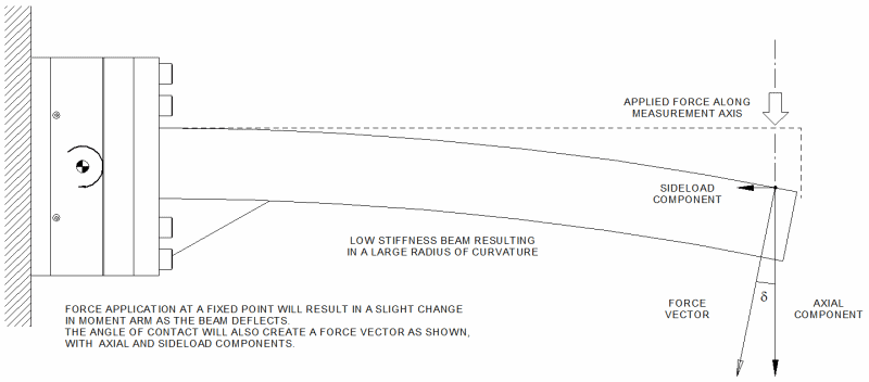
It is difficult to give an accurate uncertainty figure for our cantilever moment rig. The error evaluations obtained from it will at least be conservative and the loadcells will be likely to perform even better in real world applications. With a moment arm of increased stiffness, the error would be a factor better than given. However, such a moment arm would probably be extremely heavy and the tare mass would be rather large. In either case, an applied load error of less than 1% over half a metre is exceptional when considering the error characteristics of an F319 handbrake loadcell, which gives a nominal applied load error of less than 1% over the width of a person’s palm. The geometry of the F320 beam structure also gives an excellent natural immunity to sideloads. This is comparable to the active gauge compensation characteristics of the F300, such that:
![]()
When installing an F320 loadcell, it should be noted that the 8-off fixing holes at either side are blind holes of limited thread depth. Therefore, to ensure data-sheet performance, the correct thread engagement should be used, (10mm nominal). The correct torque values for the screws should also be used. These are 46Nm when using plated screws or 61Nm for screws that have not been plated. We would usually recommend using screws that are grade 10.9 or better. The size and quantity of these fixings are deliberately over-rated in order for the full cantilever moment arm of 500mm to be used, without the bolts being the weakest link, even when overloaded within the safe limits. The loadcell will therefore always display zero-shift long before a critical load is applied. This is a standard safety feature for this type of loadcell.
Bear in mind that any moment greater than the specified maximum, may cause irreversible zero-shift. This is where the loadcell does not return to a perfect zero when the applied load is removed. Our engineers will be happy to discuss special variants where full load at half a metre is not enough for your proposed application, or where special calibrations are required. Note that even a very small axial load at a great distance may generate an excessive moment. With our cantilever moment arm rig, we are able to offer calibrations at any moment arm length up to one metre. This is beneficial if the loadcell is to be used at a fixed moment arm or centred around a point such as with the examples shown in page 1 diagrams. We are also happy to offer loadcells designed to take larger moment arm lengths, but will be unable to offer a full quantified calibration above the one metre length.
Worked Example
A 5kN F320 bracket loadcell is used to support a vertical strut and paddle arrangement for a wave tank drag force application (see diagram on page 1). When the water is at its minimum depth, 1kN drag force acts through a centre of pressure that is 1100mm from the loadcell face. ( This is acceptable as the combination neither exceeds the rated load of the loadcell or the maximum permissible moment). When the water is at its full depth, 1.75kN drag force acts through a centre of pressure that is 800mm from the loadcell face. The maximum potential errors for the two instances are as shown below.
At minimum depth:
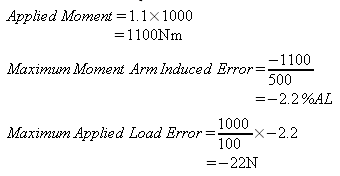
Hence the loadcell may read as low as 978N for a 1kN applied load.
At maximum depth:
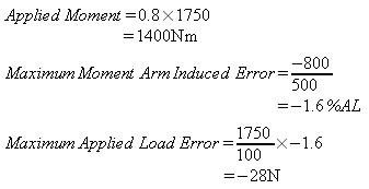
Hence the loadcell may read as low as 1722N for a 1.75kN applied load.
The actual deviation from the applied load is greater in the second load case. However, in terms of error as a percentage of the applied load, the loadcell is inherently more accurate at smaller moment arms. This is despite the moment itself being greater for the second load case.
If the F320 loadcell had been calibrated at the mid range of the possible moment arms, in this case 950mm, the perceived errors would be significantly smaller. (Note that 950mm is just within our calibration capacity).
At minimum depth:
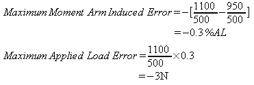
Hence the loadcell may read as low as 997N for a 1kN applied load.
At maximum depth:

Hence the loadcell may read as low as 1755.25N for a 1.75kN applied load.
By calibrating mid range, the percentage applied load errors become even about this midpoint. The errors in this case are also generally much smaller. This is why we always endeavour to accurately replicate the real world application with our calibrations. It is advisable to discuss the mechanics with our engineers prior to purchase so that we can offer the best service possible.
