The F307 loadcell provides a bi-directional direct measurement of the X, Y and Z components resulting from a force vector. Apart from error evaluations, each output is pure and requires no mathematical manipulation. For the standard loadcell the range applies to each axis.

Rigid Body Or Free Body Applications
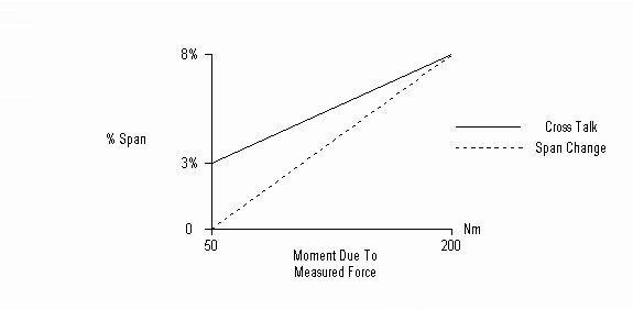
All multi-axis force sensors suffer from ‘cross talk’ errors which are explained below. The cross talk error is present in all loading cases but will vary in magnitude depending upon the force centre position and any resulting bending moments or couples applied to the loadcell. In rigid body applications, these couples are negligible and the cross talk error is as specified in the data-sheet.
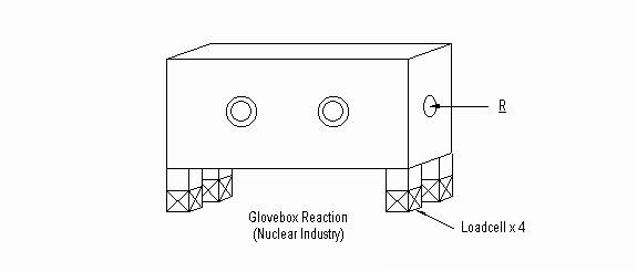
Typical Rigid Body Application

Due to the rigid structure the reaction forces are translated to the four loadcells without imparting significant couples or bending moments.
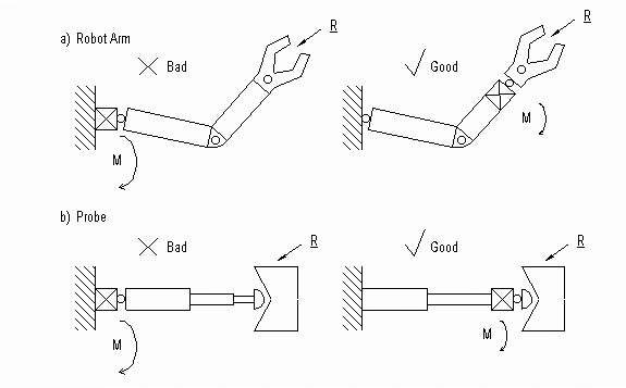
Typical Free Body Applications

A free body application usually employs one loadcell with a force centre with an offset origin or an extended axial origin. A free body application may impart couples or moments upon the loadcell and this will effect the cross talk and span as described below.

Structural Limits
The F307 is designed to operate to a maximum of all three axis fully loaded simultaneously.
Overload Moment – Safe: The maximum static moment applied at the active boss that the F307 can survive without permanent damage. Note that some bridge output zero shift may occur.
Overload Moment – Ultimate: The maximum static moment applied at the active loadcell boss before structural failure occurs.
Cross Talk
All multi-axis loadcells suffer from mechanical coupling between the mutually perpendicular sensing axis i.e. if axis X is loaded, a small effect is witnessed on the output of Y and Z axis. This effect is minimized by a full load application on any or both of the other axis. The uncertainty is, therefore, expressed as the maximum case. The F307 cross talk uncertainty for rigid body applications, where moments are considered negligible, is 3%. The 3% applies to the output span of each individual axis.
e.g. X + Ve span = 20 mV Uncertainty at 3% is 0.6 mV
This maximum uncertainty exists if Y, Z or both are fully loaded.
The user is left to estimate the cross talk uncertainty for specific load conditions. If these conditions are known in advance, we can carry out a specific cross talk evaluation.
Fixings
The active boss is keyed to allow locking against moment induced rotation.
Base fixings are inert and do not effect the three bridge zero outputs or performance. Base flatness tolerance should be matched by the mating surface at ± 0.05mm flatness tolerance.
Recommended fixing torque using 8.8 grade fixings
Output boss: 40Nm
Base fixings: 40Nm
Calibration Force centre
Using the input boss centre as origin the calibration force centre has the co-ordinates (0, 0, 5)mm, (x, y, z)mm. The 5mm allows for a 10mm thick planar load plate. This equates to a typical application structure.
