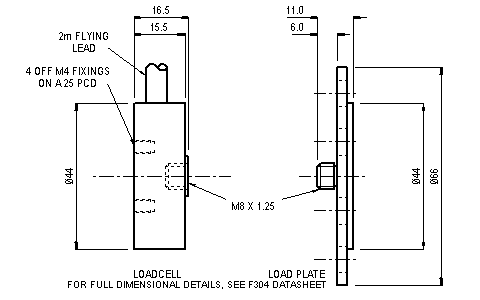
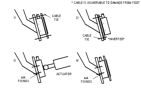
The F304 is based upon a cruciform beam structure with eight strain gauges configured to provide a high degree of off axis compensation during ergonomic use. The cruciform structure is superior to simple diaphragm based loadcells, which are inherently prone to off axis loading induced errors. The high performance provides for a loadcell that can be used with confidence ergonomically and mechanically without the foot application load plate. The dual ergonomic and mechanical fixings have been used together in the collection of real load data, ergonomic, which is later used to control an actuator by providing the force feedback in a closed loop control system using the loadcells mechanical fixings.
Assembly Drawing

Fixing Arrangements

Error Assessment
Please refer to the F304 data-sheet for mechanical fixing performance details.
a. Cable Ties: When used as in case number 1 in the fixing arrangement drawing load typical nylon cable ties can produce a 2mV zero shift. This is equivalent to 10% of the rated load. This can normally be tared off in the monitoring electronics. Data-sheet performance is maintained for nett loads above 5% of the rated load. Below this point zero return is retarded due to the cable ties equilibrating.
b. Ergonomic Extremes: Re-creating the most extreme degree of foot misplacement, with 50% of the friction pad in contact with the foot print, span errors of 0.5% of rated load have been observed. With a normally placed foot the performance is as detailed in the data-sheet specification.
Special Versions
Any load range compatible with the size 1 F256 loadcell can be produced although the industry standard is a 2.5kN full range.
Special versions produced so far include:
a. Custom end fixings.
b. Underside mounting. With minor modification to the brake pedal the loadcell can be mounted on the underside and be driven by a shaft and pad assembly passing through the pedal. This arrangement retains the ergonomic geometry of the product design.
