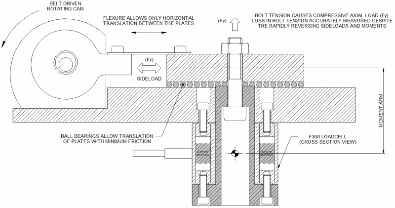
The F300 is based upon a highly symmetrical beam structure, with eight strain gauges configured to provide a high degree of off axis compensation and sideload rejection. This symmetrical beam structure is superior to simple cylindrical/’donut’ loadcells, which are inherently prone to off axis loading and sideload induced errors. As such, the F300 loadcell fills a commonly found gap in force sensor products. It retains the geometrical benefits of donut types, for applications such as through bolt testing, whilst offering extraneous force immunity and an overall performance specification that rivals our best products. An excellent example application is the Junkers test machine.
F300 Example Application – Junkers Test Machine
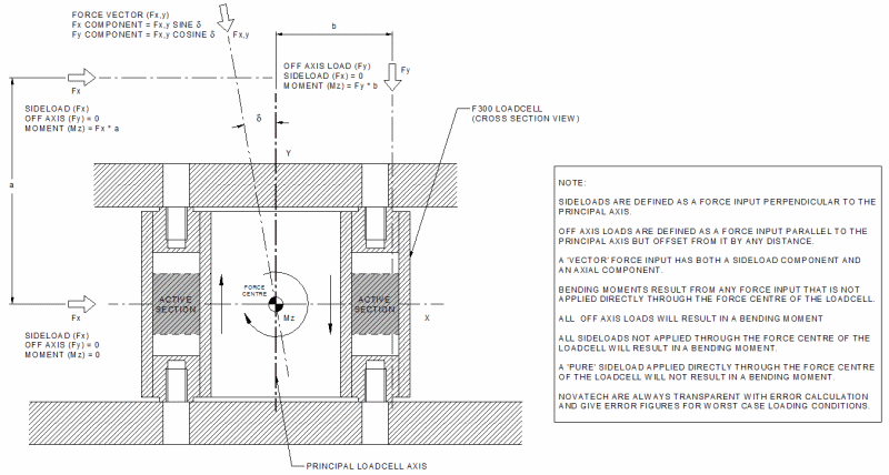
Extraneous Force Definition
In terms of force sensors, extraneous forces are defined as any force input to a loadcell that is not along the principal axis. This is the axis along which the loadcell is designed to be loaded. Note that where a uniform force is exerted over a large area, it is the centre of the force that must be in line with the principal axis. Typically, extraneous forces are the result of two main components, sideloads and off axis loads. In combination these may cause vectors and/or moments as shown in the accompanying diagram.
Error Assessment
Moments can be particularly detrimental in force measurement and will often heavily influence the output from a standard bridge circuit. Worse still, it is possible to have a large moment without being fully aware of the extent of the problem, as even a small sideload at a reasonable distance can cause a sizeable moment. For this reason, it is desirable to have known and predictable behaviour with respect to applied sideloads and moments. Where these characteristics are given for a Novatech product, the moment itself has been induced by a sideload rather than an off axis load. This is the more extreme application and is therefore the most useful and honest way to present the error. It should be noted that it is increasingly common with other manufacturers for error values to be given in terms of moments induced by off axis loads, as this makes any errors look smaller.
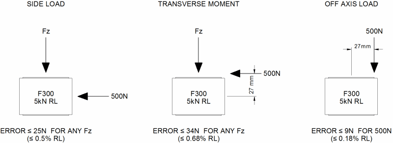
For the F300 loadcell we are able to give the following extraneous force characteristics that are true across the entire standard data-sheet range:
Total Maximum Error is the sum of both sideload and moment induced errors.
Off axis Load Induced Error is equal to the Total Error, where the sideload component is zero. Hence Off axis Load Induced Error is equal to the Moment Induced Error.
Vector Induced Error is equal to the Total Error, where the sideload component has a cosine term relating to the effective angle of applied load.
Note that off axis loads in this case are limited to those applied within the loadcell footprint, subject to the maximum permissible moment. If this condition cannot be met, the F320 loadcell may be an option.
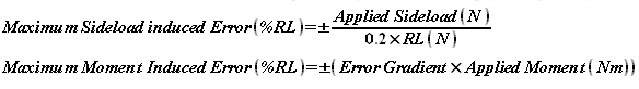
Sideload and moment errors are given by the following principal equations:
F300 Quick Reference Chart for use with the Moment Induced Error equation
| Rated Load | 1kN | 2kN | 5kN | 10kN | 20kN | 50kN | 100kN | 200kN |
|---|---|---|---|---|---|---|---|---|
| Max. Moment | 13.5Nm | 27Nm | 67.5Nm | 225Nm | 450Nm | 1125Nm | 3375Nm | 6750Nm |
| Error Gradient | 0.056 | 0.0302 | 0.0133 | 0.007180 | 0.00387 | 0.00171 | 0.000919 | 0.000495 |
The equations given above deal only with the maximum possible error figures, (as defined by the boundaries of a ‘cone of error’ such as in the example graphs that follow). From extensive testing it has been found that certain orientations will tend to provide superior error compensation due to the compound effect of gauge alignment and machining tolerance. For an application where error compensation is particularly critical along a defined axis and/or the extraneous forces act along a single axis only, Novatech are happy to undertake a quick test to provide the user with the optimum orientation for their loadcell. Full ‘EFI’ reports and custom calibration checks at specific moment arms are also available and are priced on request. Calibrating to a set of specific conditions will greatly reduce the perceived error for any given application. Note that the immunity of the 8 gauged F300 loadcell to applied torque loads is largely comparable to our standard products. For improved torque performance it is suggested to switch to a bridge circuit of 16 gauges. It is advised to discuss all individual requirements with our engineering staff.
When installing an F300 loadcell, it should be noted that the 8-off fixing holes at either end are blind holes of limited thread depth. Therefore, to ensure data-sheet performance, the correct thread engagement should be used as given in the following table. The correct torque values for the screws are also provided. The size and quantity of fixings are deliberately over-rated for the full scale axial load in order to allow large moments to be applied, without the bolts ever being the weakest link, even when overloaded within the safe limits. The loadcell will therefore always show a large zero-shift long before a critical load is applied. This is a standard safety feature for this type of loadcell.
F300 Fixing Requirements for data-sheet Performance
| Thread | Minimum/maximum thread engagement |
Torque for plated screws (grade 10.9 or better) |
|
|---|---|---|---|
| Size 1 | M5 | 5 / 7.5mm | 7.1Nm |
| Size 2 | M8 | 8 / 12mm | 29.0Nm |
| Size 3 | M12 | 12 / 18mm | 101.0Nm |
Error Evaluation
Error evaluation during product development was conducted in accordance to a strict methodology. Prototype loadcells were calibrated to our usual high standards to obtain control data, before being subjected to a fixed percentage of their ultimate extraneous force capacity. Sideload and moment combination tests alone generated 128 data points for each loadcell in order to fully characterise their behaviour. This multitude of data was tabulated and manipulated using straight line maths in order to separate the sideload component from the moment induced error. A graphic representation of the typical sideload and moment induced error for a 50kN loadcell is shown below. The graphs show the data for a complete 360° sweep of tests around the principal axis in 45° increments.
F300 50kN Prototype Results for Sideload and Moment Induced Errors
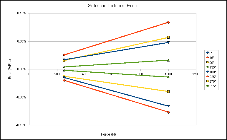
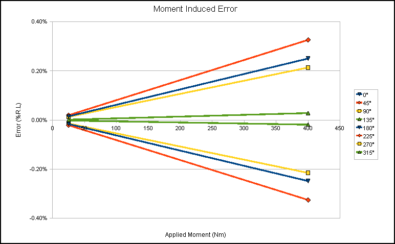
The graphs show that the sideload induced error is less significant when compared to the moment induced error and that the loadcell is generally extremely good at rejecting sideloads. An apparently large variation is seen between one orientation and the next, although this is in fact a ±0.08% RL variation across a full 360° sweep and is due to acceptable gauge positioning and machining tolerances. This variation is naturally amplified by moment effects. Even so, the moment induced error is both extremely linear and reversible, such that errors for 0° and 180°, for example, are equal and opposite. This allows the maximum errors to be expressed using y = mx + c where c = 0.
For the loadcell given in this example, the formulae worked out from the graphs to be as shown below.
![]()
![]()
These formulae work together in parallel such that, for this particular loadcell, a sideload of 800N applied at a moment arm of 500mm would give a combined maximum error of 0.384% RL
The moment induced error formula also works for off axis loads as the sideload component is zero.
For example, full scale load applied at a 25mm offset would give a maximum of 1%RL error.
Once the testing of all prototypes had been completed, trend lines of errors against load range could be plotted. The trend lines are conservative and therefore err on the side of more error than is truly likely to be seen. These subsequently yield the formulae/relationships given earlier in this engineering sheet. You will notice that the 50kN prototype given in the example performed better than the principal equations suggest. For example if the standard error gradient is used, the error for 25mm off axis would be 2.1%RL. This is an indication of the conservative nature of our analysis and why we suggest a full EFI report. These reports are invaluable if you require detailed documentation of the precise errors for each orientation of a purchased loadcell, over a range of sideloads and moments.
Worked Example
A potential customer is considering a new loadcell for their application. They wish to measure 17kN axial force and will therefore require a 20kN loadcell. A typical choice might be an F256 loadcell due to its good overall performance. However, they expect to see varying sideload between 100 and 500N at a fixed moment arm of 280mm. It is important for them to know the likely measurement error before they commit to purchasing a new loadcell. Using the information herein, they evaluate the maximum errors for 100 and 500N sideload.
For a 20kN loadcell we expect the moment induced error to be ±(0.00387 x Applied Moment (Nm))
Hence:
For 100N sideload:
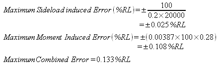
This would relate to the customers application as 133.4N error in a 17000N measurement.
For 500N sideload:
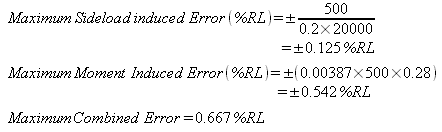
The customer decides they require less than 0.5%RL total error. They are able to achieve this by redesigning the system and limiting the moment arm to less than 190mm. However, they decide to purchase a loadcell with an EFI report for 500N sideload before making any changes. The error is found to <0.5%RL for all orientations and is <0.2%RL in a particular orientation. The customer is able to fit the loadcell in the best orientation and use the system without redesign.