
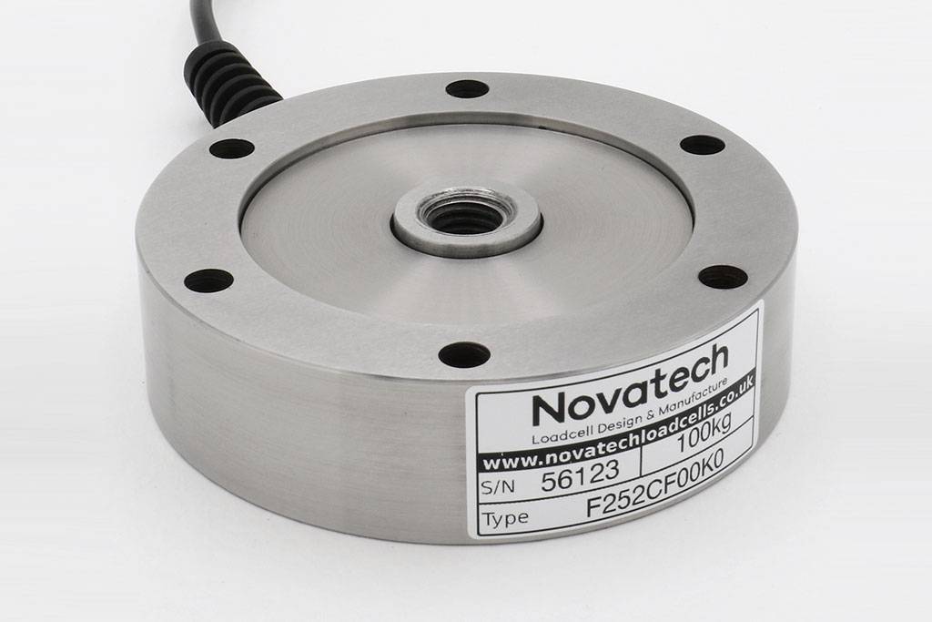
F252 Pancake Loadcell
Standard Ranges 1, 2, 4, 8 and 10kN (100kgf to 1tonnef)
- Tension / compression / bi-directional calibration
- Compact size
- Low deflection
- Hardened stainless steel body
- Traceable calibration with certificate included in the standard price
- Standard 1 year warranty
Specification
Parameter | Value | Unit |
Non-linearity - Terminal | ±0.1 | % RL |
Hysteresis | ±0.1 | % RL |
Creep - 20 minutes | ±0.05 | % AL |
Repeatability | ±0.02 | % RL |
Rated output - Nominal | 1.6 | mV/V |
Rated output - Rationalised | 1.5 | mV/V |
Rationalisation tolerance (applies to single direction calibrations) | ±0.5 | % RL |
Zero load output | ±4 | % RL |
Temperature effect on rated output per °C | ±0.005 | % AL |
Temperature effect on zero load output per °C | ±0.02 | % RL |
Temperature range - Compensated | -10 to +50 | °C |
Temperature range - Safe | -10 to +80 | °C |
Excitation voltage - Recommended | 10 | V |
Excitation voltage - Maximum | 20 | V |
Bridge resistance up to 400kgf | 350 | Ω |
above 400kgf | 700 | Ω |
Insulation resistance - Minimum at 50Vdc | 500 | MΩ |
Overload - Safe | 50 | % RL |
Overload - Ultimate | 100 | % RL |
Weight - Nominal (excluding cable) | 840 to 940 | g |
All standard ranges are manufactured in stainless steel.
Geometry: Low profile axial loadcell for use in force measurements in tension and compression.
With bi-directional versions there is a small difference between the output signal for compression and tension. All standard bi-directional loadcells are calibrated in both modes and the output for each direction is stated on the test / calibration certificate.
The F252 is ideal for engineering force measurements particularly in applications where there is a limit on the height of the loadcell. It can be used for test machines and a wide range of general industrial applications.
We are happy to design variants of this loadcell to meet your specific requirements. Versions can be manufactured for fully compensated operation up to +250°C. Please consult our engineering department.
Order Codes
Code | Description |
F252CF00K0 | Compression, unrationalised |
F252TF00K0 | Tension, unrationalised |
F252UF00K0 | Bi-directional, unrationalised |
F252CF00KN | Compression, rationalised |
F252TF00KN | Tension, rationalised |
F252UF00KN | Bi-directional, rationalised |
Structural Stiffness - Nominal
Range (kN) | Stiffness (N/m) |
1 | 3.0 x 10⁶ |
2 | 6.0 x 10⁶ |
4 | 1.2 x 10⁷ |
8 | 2.4 x 10⁷ |
10 | 3.0 x 10⁷ |
Notes
- AL = Applied load.
- RL = Rated load.
- Temperature coefficients apply over the compensated range.
- The load must be applied directly through the central loading axis.
Connections
The loadcell is fitted with 2 metres of PVC insulated 4 core screened cable type 7-2-4C.
Excitation + = Red, Excitation - = Blue, Signal + = Yellow, Signal - = Green, Screen = Orange.
Reverse the signal connections to obtain a positive signal in tension mode. The screen is not connected to the loadcell body.