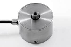
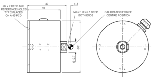
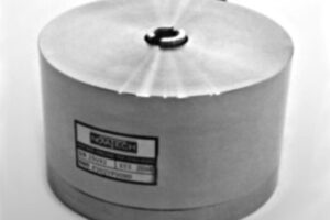
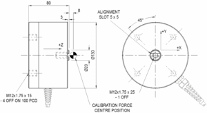
Home » Products » Loadcells » Multi-Axis » F307 3 Axis Loadcell
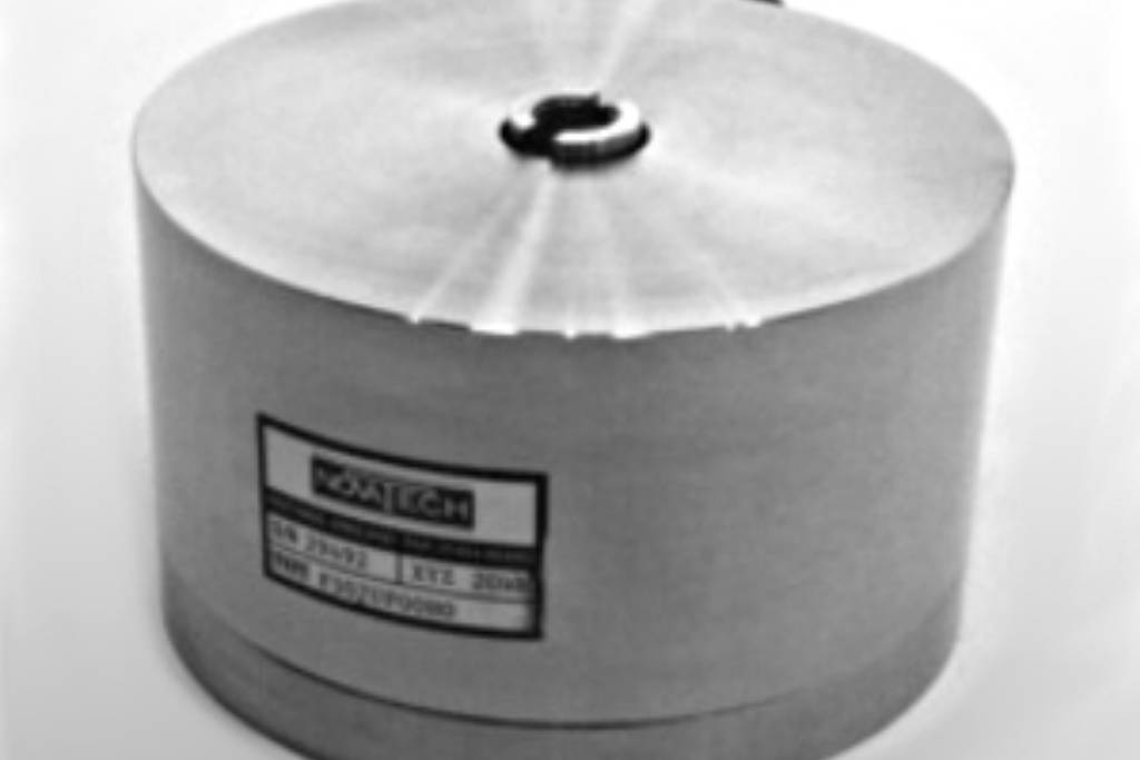
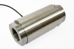
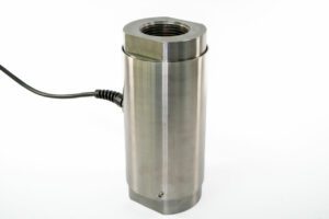
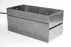
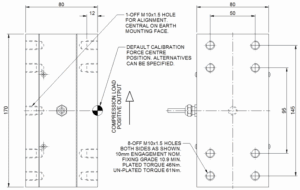
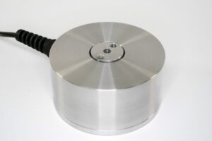
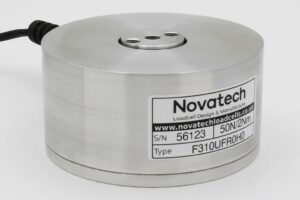
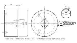
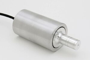
The F307 is ideally suited to many industrial and scientific applications, including automotive research. The performance specification is valid for moments up to 50Nm. For applications up to 200Nm please see the F307 Engineering Application Sheet.
The loadcell can be manufactured with force ranges to suit the application. The axes can have different force ranges. Please consult our engineering department about the viability of the required ranges.
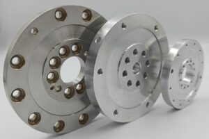
We are happy to design variants of this loadcell to meet your specific requirements. Versions can be manufactured for fully compensated operation up to +250°C. Please consult our engineering department.
Up to 50Nm within its performance specification, while the F307 Engineering Application Sheet covers applications up to 200Nm. Check the application sheet if your setup exceeds 50Nm. As structural limits, the safe overload moment is 250Nm and the ultimate overload moment is 500Nm.
Yes. The F307 gives a bi-directional direct measurement of the X, Y, and Z components of a force vector, and it is supplied as a bi-directional, unrationalized unit as standard. Its good output symmetry also simplifies calibration of the instrumentation you connect to each axis.
Through a 25-pin D-type plug on 2 meters of 12-core screened PVC cable. Each axis has its own excitation and signal pins: X uses pins 1 to 4, Y uses 9 to 12, and Z uses 14 to 17, with the screen on pins 5, 13, and 18, so all three axes run through a single connector.
| Parameter | Value | Unit |
|---|---|---|
| Non-linearity - Terminal | ±0.3 | % RL |
| Hysteresis | ±0.4 | % RL |
| Creep - 20 minutes | ±0.1 | % AL |
| Repeatability | ±0.02 | % RL |
| Maximum cross talk | 3 | % RL |
| Rated output - Nominal | 1.5 | mV/V |
| Zero load output | ±4 | % RL |
| Temperature effect on rated output per °C | ±0.005 | % AL |
| Temperature effect on zero load output per °C | ±0.007 | % RL |
| Temperature range - Compensated | -10 to +50 | °C |
| Temperature range - Safe | -10 to +80 | °C |
| Excitation voltage - Recommended | 10 | V |
| Excitation voltage - Maximum | 10 | V |
| Bridge resistance | 700 | Ω |
| Insulation resistance - Minimum at 50Vdc | 500 | MΩ |
| Structural stiffness - X and Y | 6.2 x 10⁷ (10kN) / 6.6 x 10⁷ (20kN) | N/m |
| Structural stiffness - Z | 8.7 x 10⁷ (10kN) / 9.4 x 10⁷ (20kN) | N/m |
| Overload - Safe | 50 | % RL |
| Overload - Ultimate | 100 | % RL |
| Overload moment - Safe | 250 | Nm |
| Overload moment - Ultimate | 500 | Nm |
| Weight - Nominal (excluding cable) | 3.1 | kg |

| Code | Description |
|---|---|
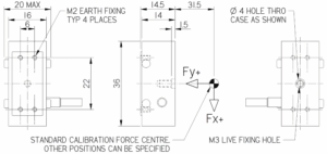
| F307UF00K0 | Bi-directional, unrationalised |
| The F307 is fitted with 2 metres of PVC insulated 12 core screened cable, type 7-1-12C, terminated with a 25 pin D type plug. The screen is not connected to the loadcell body. |
| Function | Wire colours and pin numbers | |||||
|---|---|---|---|---|---|---|
| X axis | Y axis | Z axis | ||||
| Excitation + | Red | 1 | Violet | 9 | Orange | 14 |
| Excitation – | Blue | 2 | Black | 10 | Turquoise | 15 |
| Signal + | Yellow | 3 | Brown | 11 | Pink | 16 |
| Signal – | Green | 4 | White | 12 | Grey | 17 |
| Screen | Orange (thick) | 5, 13 and 18 | ||||