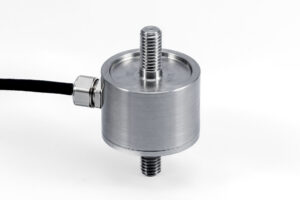
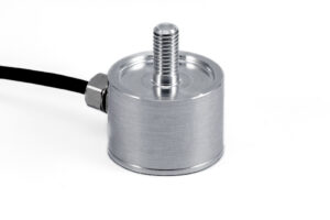
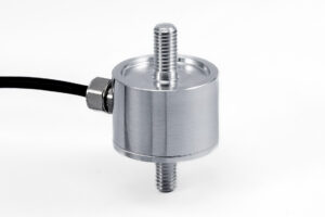
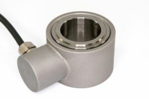
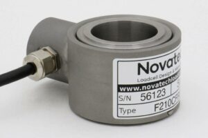
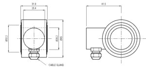
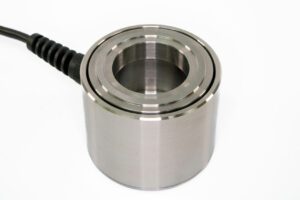
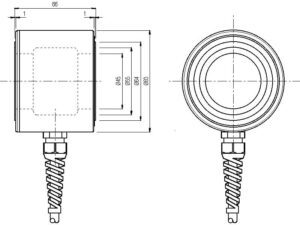
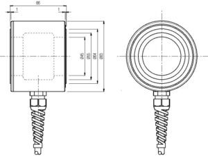
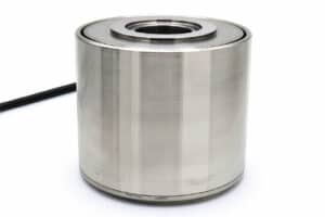
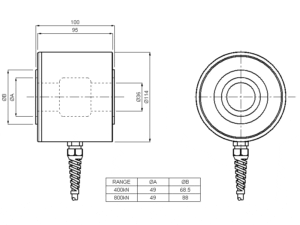
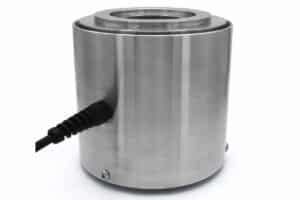
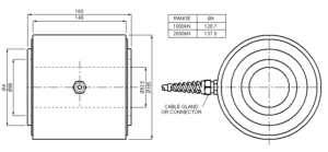
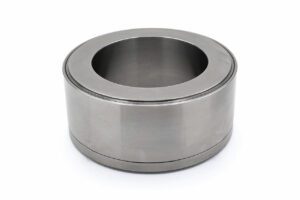
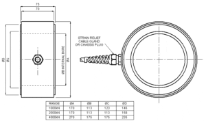
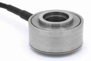
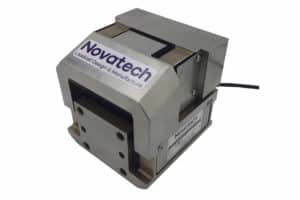
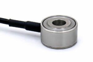
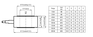
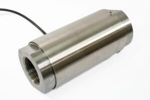
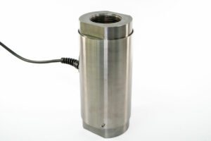
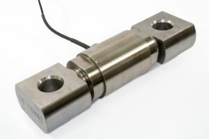
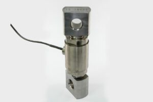
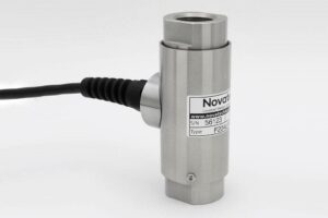
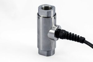
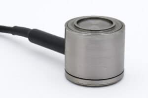
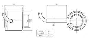
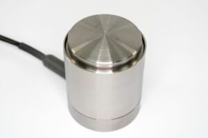
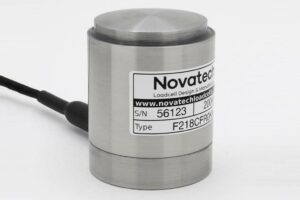
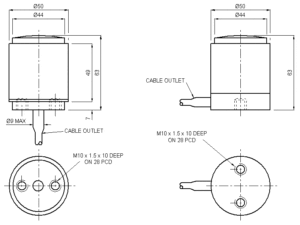
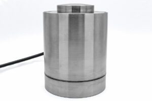
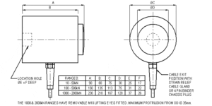
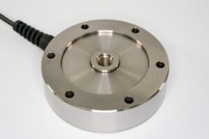
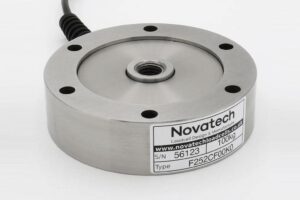
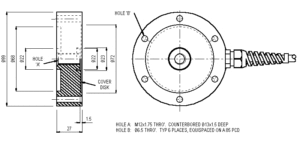
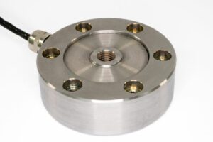
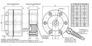
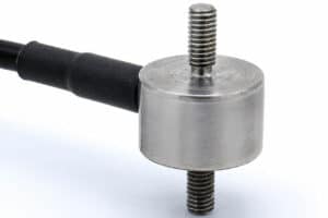
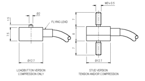
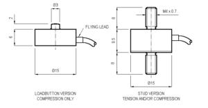
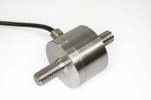
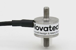
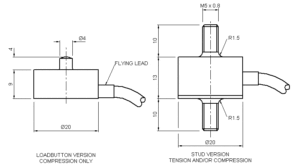
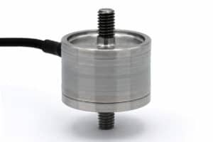
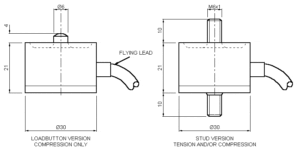
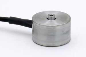
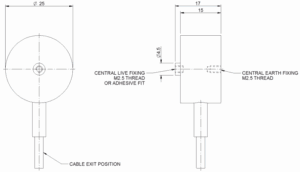
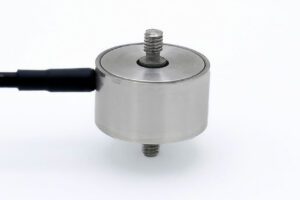
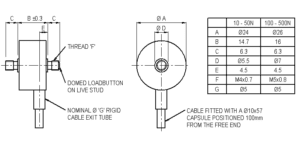
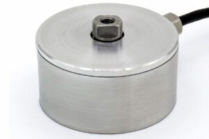
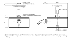
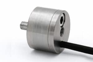
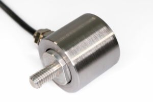
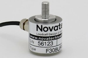
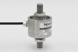
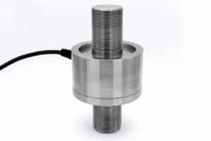
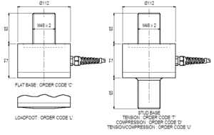
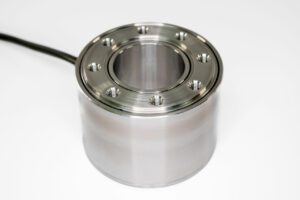
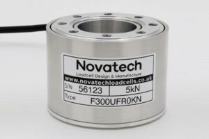
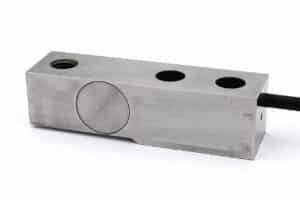
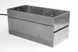
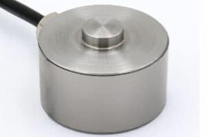
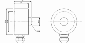
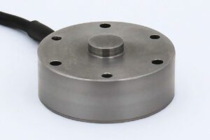
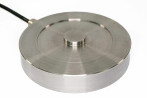
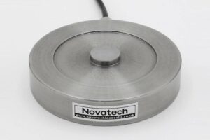
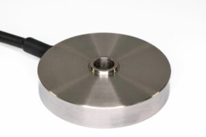
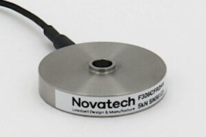
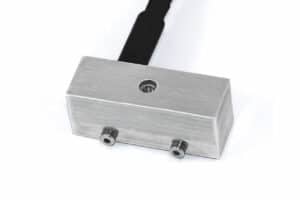
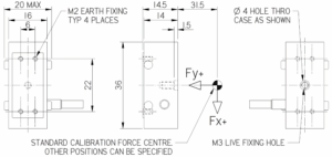
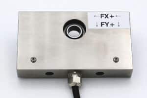
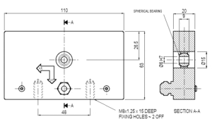
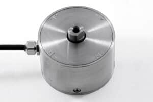
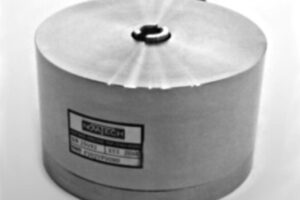
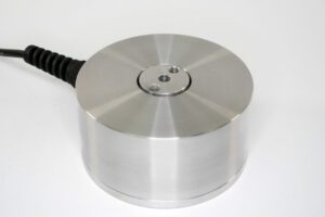
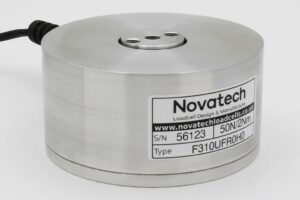
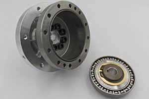
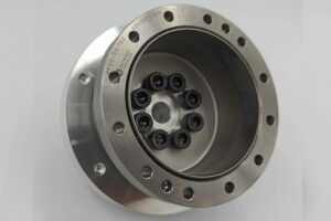
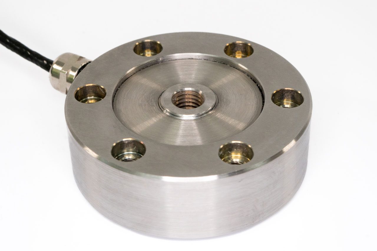
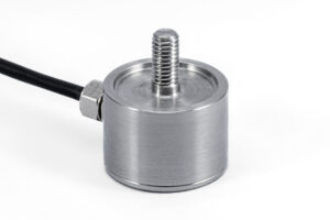
The F318 features a shear-web construction engineered to provide exceptional stiffness both axially and laterally, making it suitable for demanding measurement environments. This structural arrangement supports the performance expected from universal pancake load cells, especially in applications requiring compact form factors without compromising mechanical integrity.
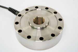
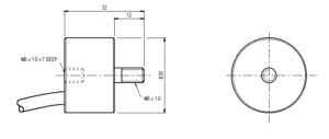
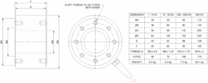
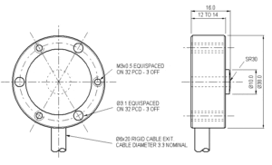
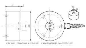
A key advantage of the F318 is its balanced response when used in either compression or tension. Each bi-directional unit undergoes calibration in both loading directions, ensuring dependable and repeatable output across its full operating envelope. For capacities up to 20kN, the design incorporates counter-bored and threaded outer mounting points, allowing flexible installation while preserving the low-profile geometry.
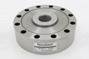
This model includes a recessed loading boss as standard. For applications that require a raised boss instead, the F254 series may be a more appropriate option; that range is available in capacities from 25kN to 200kN and aligns with many of the functional expectations associated with universal pancake load cells.
Custom engineering support is available for projects requiring modified geometry, tailored mounting provisions, or extended operating conditions. Special versions can be produced with full compensation for temperatures reaching +250°C, and our engineering team can advise on how best to configure the sensor for your application. Additional information on other load cell types and families is available in the Load cell Specifier Guide.
Overall, the F318 provides a rugged, low-height measurement solution suitable for users who need reliable performance in both compression and tension within a compact shear-web design.
Yes. The F318 is calibrated bi-directionally, providing balanced and reliable output in both compression and tension. Each unit is individually verified to ensure repeatable measurements across its full capacity range, maintaining precision in demanding applications.
Absolutely. We can modify the F318 with tailored mounting options, altered geometry, or specific loading interfaces. Our engineering team evaluates each request to ensure feasibility while preserving measurement accuracy and the structural integrity of the pancake load cell.
Yes. Custom versions of the F318 can be manufactured with full compensation for temperatures up to +250°C. This ensures consistent performance and reliable readings even in elevated temperature applications, making it suitable for demanding industrial or laboratory settings.
| Parameter | Value | Unit |
|---|---|---|
| Non-linearity - Terminal | ±0.1 | % RL |
| Hysteresis | ±0.1 | % RL |
| Creep - 20 minutes | ±0.05 | % AL |
| Repeatability | ±0.02 | % RL |
| Rated output - Nominal | 2.1 | mV/V |
| Rated output - Rationalised | 2 | mV/V |
| Rationalisation tolerance (applies to single direction calibrations) | ±0.1 | % RL |
| Output symmetry | ±0.5 | % AO |
| Fatigue life (ranges 10kN and above) | 108 | RL cycles |
| Zero load output | ±4 | % RL |
| Temperature effect on rated output per °C | ±0.005 | % AL |
| Temperature effect on zero load output per °C | ±0.005 | % RL |
| Temperature range - Compensated | -10 to +50 | °C |
| Temperature range - Safe | -10 to +80 | °C |
| Excitation voltage - Recommended | 10 | V |
| Excitation voltage - Maximum | 20 | V |
| Bridge resistance | 700 | Ω |
| Insulation resistance - Minimum at 50Vdc | 500 | MΩ |
| Fixing bolt torque | See outline drawings. | Nm |
| Overload - Safe | 50 | % RL |
| Overload - Ultimate | 200 | % RL |
| Sealing | IP65 |
| Code | Description |
|---|---|
| F318CFR0K0 | Compression, IP65, unrationalised |
| F318TFR0K0 | Tension, IP65, unrationalised |
| F318UFR0K0 | Bi-directional, IP65, unrationalised |
| F318CFR0KN | Compression, IP65, rationalised |
| F318TFR0KN | Tension, IP65, rationalised |
| F318UFR0KN | Bi-directional, IP65, rationalised |
| Change the F to a P for the connector version. |
| Range (kN) | Stiffness (N/m) |
|---|---|
| 1 | 1.6 x 10⁷ |
| 2 | 1.1 x 10⁸ |
| 5 | 3.8 x 10⁸ |
| 10 | 1.6 x 10⁹ |
| 20 | 1.3 x 10⁹ |
| 50 | 1.9 x 10⁹ |
| 100 | 4.5 x 10⁹ |
| 200 | 9.5 x 10⁹ |
| 500 | 1.3 x 10¹⁰ |
| Title | Type | File |
|---|---|---|
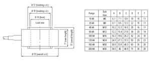
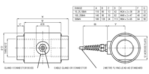
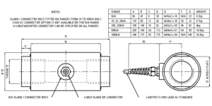
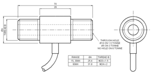
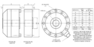
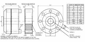
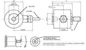
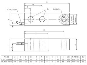
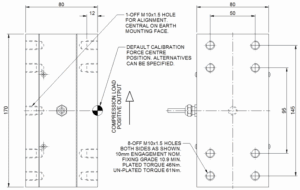
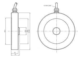
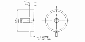
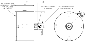
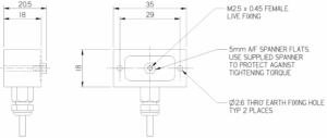
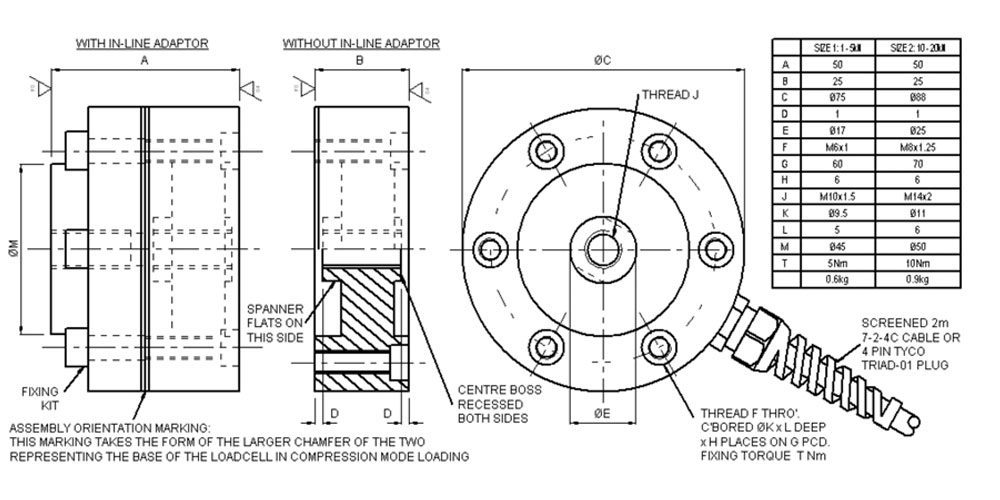
| Outline drawing of F318 size 1 and 2. (1 to 20kN.) | Outline | Download |
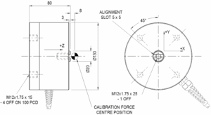
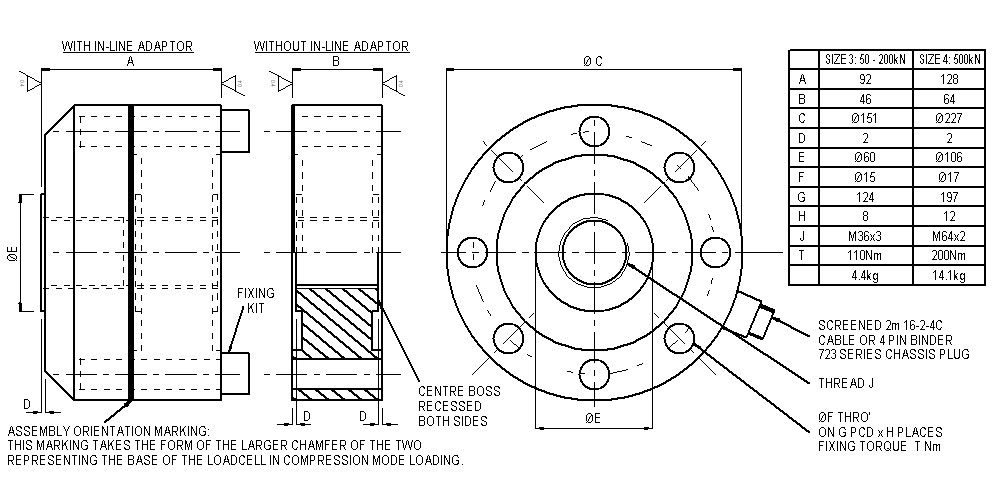
| Outline drawing of F318 size 3 and 4. (50 to 500kN.) | Outline | Download |
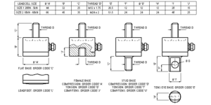
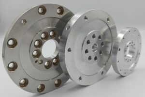
| Socket plates. | Fittings | Download |
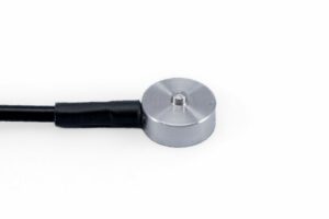
| Loadbutton | Fittings | Download |
| F318-T/C/U-FR0K0 1 to 5kN (100 to 500kgf) | STEP File | Download |
| F318-T/C/U-FR0K0 10 to 20kN (1 to 2tonnef) | STEP File | Download |
| F318-T/C/U-FR0K0 50 to 200kN (5 to 20tonnef) | STEP File | Download |
| F318-T/C/U-FR0K0 500kN (50tonnef) | STEP File | Download |

| F318-T/C/U-PR0K0 1 to 5kN (100 to 500kgf) | STEP File | Download |
| F318-T/C/U-PR0K0 10 to 20kN (1 to 2tonnef) | STEP File | Download |
| F318-T/C/U-PR0K0 50 to 200kN (5 to 20tonnef) | STEP File | Download |
| F318-T/C/U-PR0K0 500kN (50tonnef) | STEP File | Download |
| F318 In-line adaptor 1 to 5kN (100 to 500kgf) | STEP File | Download |
| F318 In-line adaptor 10 to 20kN (1 to 2tonnef) | STEP File | Download |
| F318 In-line adaptor 50 to 200kN (5 to 20tonnef) | STEP File | Download |
| F318 In-line adaptor 500kN (50tonnef) | STEP File | Download |
| F318 Loadbutton 1 to 5kN (100 to 500kgf) | STEP File | Download |
| F318 Loadbutton 10 to 20kN (1 to 2tonnef) | STEP File | Download |
| F318 Loadbutton 50 to 200kN (5 to 20tonnef) | STEP File | Download |
| F318 Loadbutton 500kN (50tonnef) | STEP File | Download |
| F318 Socket plate 1 to 5kN (100 to 500kgf) | STEP File | Download |
| F318 Socket plate 10 to 20kN (1 to 2tonnef) | STEP File | Download |
| F318 Socket plate 50 to 200kN (5 to 20tonnef) | STEP File | Download |
| F318 Socket plate 500kN (50tonnef) | STEP File | Download |