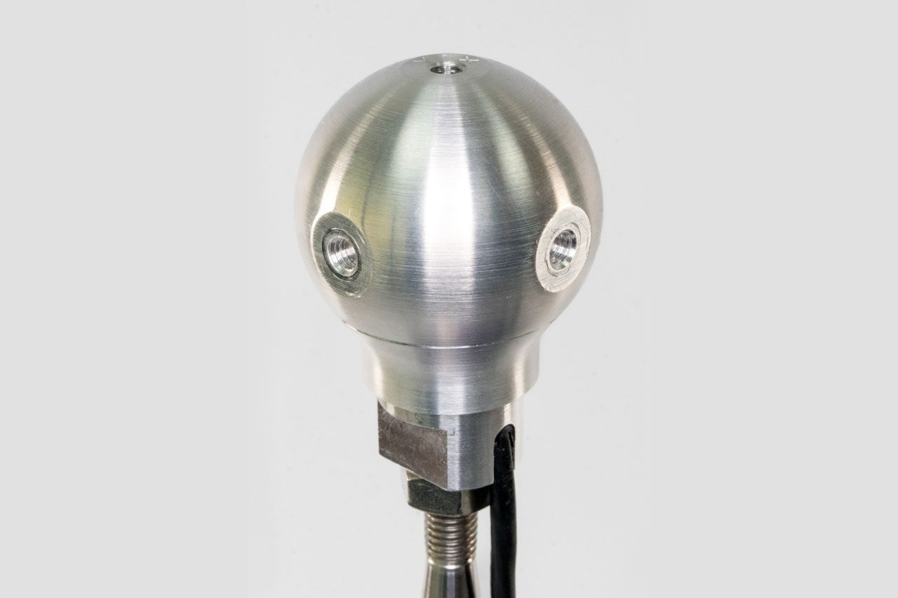
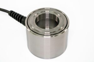
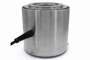
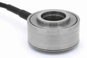
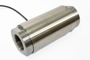
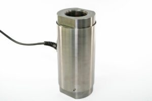
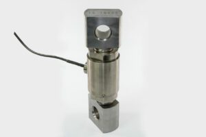
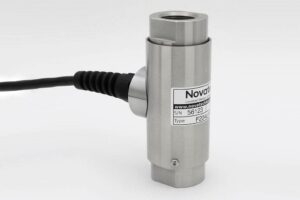
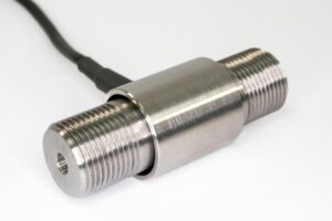
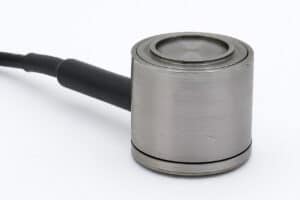
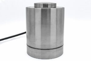
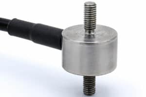
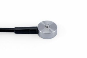
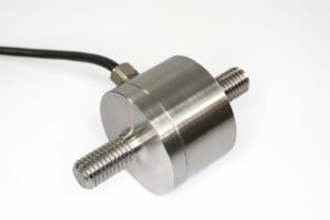
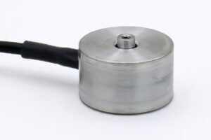
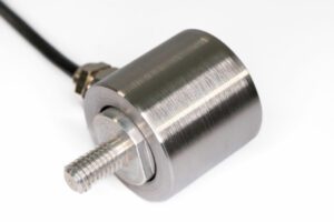
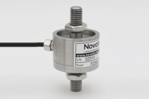
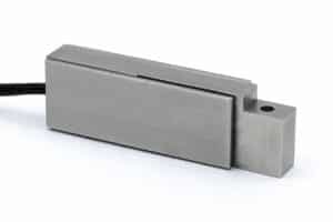
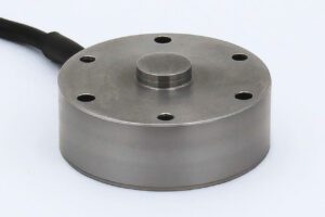
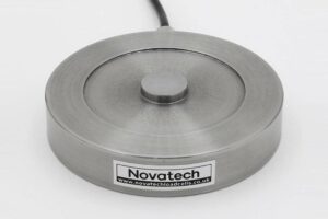
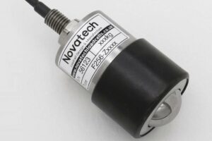
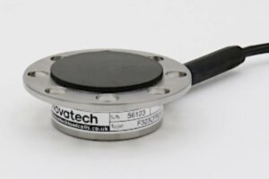
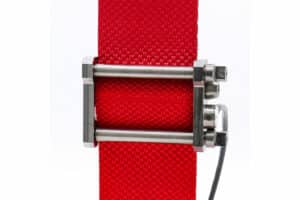
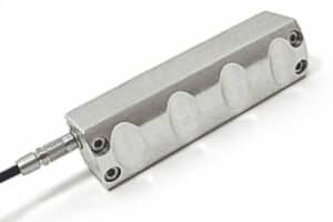
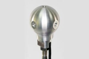
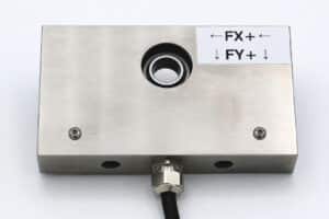
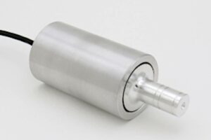
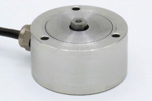
The F321 gear shift loadcell measures gear lever forces required to achieve gear selection.
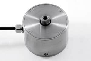
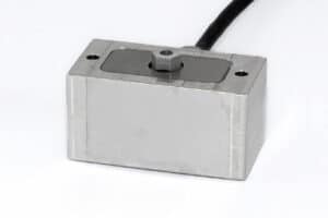
An ergonomically designed gear knob senses the force from a human hand or a mechanical actuator. The three axis force components are represented by three pure loadcell output signals. The gear shift loadcell is supplied calibrated and ready to use, no in-situ calibration or mathematical computation is required.
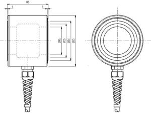
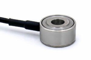
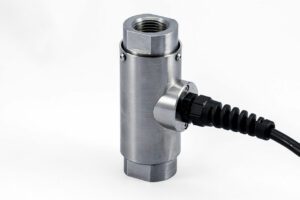
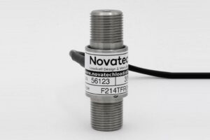
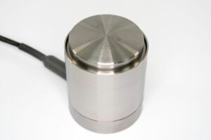
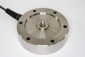
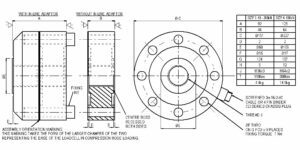
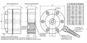
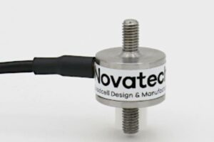
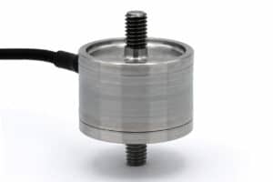
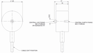
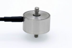
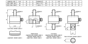
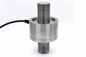
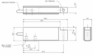
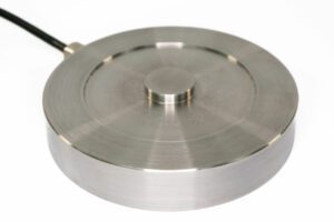
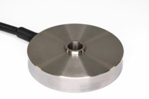
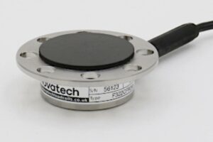
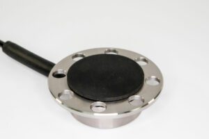
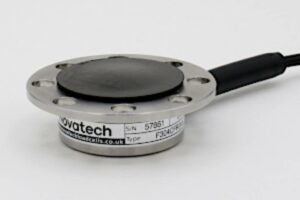
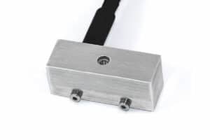
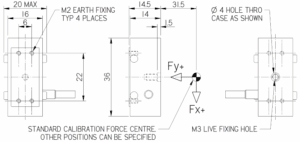
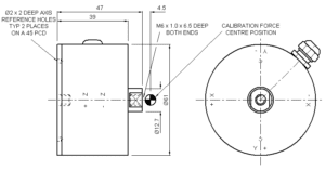
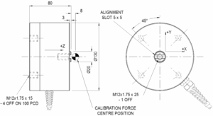
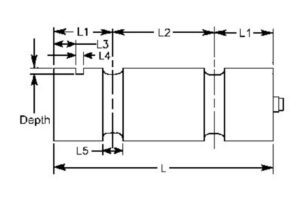
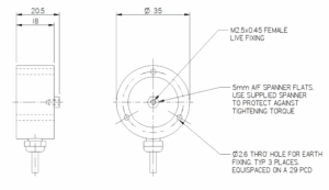
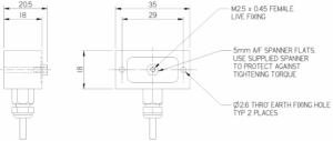
Easy fitment is achieved with mechanical axis referencing and simple attachment to a male thread or adapter.
The gear shift loadcell, like all our automotive products, can be produced for environmental test chamber temperature requirements of -40 to 80°C.
We are happy to design variants of this loadcell to meet your specific requirements. Please consult our engineering department.
An ergonomically designed gear knob senses the force from a human hand or a mechanical actuator. The three axis force components are represented by three pure loadcell output signals. The gear shift loadcell is supplied calibrated and ready to use, no in-situ calibration or mathematical computation is required.
Easy fitment is achieved with mechanical axis referencing and simple attachment to a male thread or adapter.
The gear shift loadcell, like all our automotive products, can be produced for environmental test chamber temperature requirements of -40 to 80°C.
We are happy to design variants of this loadcell to meet your specific requirements. Please consult our engineering department.
Specification
Parameter
Value
Unit
Non-linearity - Terminal
±0.5
% RL
Hysteresis
±0.5
% RL
Creep - 20 minutes
±0.1
% AL
Repeatability
±0.02
% RL
Maximum cross talk
3
% RL
Rated output - Nominal
1.0
mV/V
Zero load output
±4
% RL
Temperature effect on rated output per °C
±0.005
% AL
Temperature effect on zero load output per °C
±0.01
% RL
Temperature range - Compensated
-10 to +50
°C
Temperature range - Safe
-10 to +80
°C
Excitation voltage - Recommended
10
V
Excitation voltage - Maximum
10
V
Bridge resistance X & Y axis
350
Ω
Z axis
700
Ω
Insulation resistance - Minimum at 50Vdc
500
MΩ
Structural stiffness - Nominal - X & Y axis
2.0 x 10⁶
N/m
Z axis
1.3 x 10⁶
N/m
Overload - Safe
50
% RL
Overload - Ultimate
100
% RL
Weight - Nominal (excluding cable)
150
g
Order Codes
Code
Description
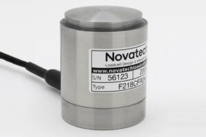
F321UF0000
Bi-directional, unrationalised
Notes
AL = Applied load.
RL = Rated load.
Temperature coefficients apply over the compensated range.
Values apply to all axes unless otherwise specified.
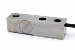
Connections
The F321 is fitted with 2 metres of PVC insulated 12 core screened cable type 7-1-12C. The screen is not connected to the loadcell body.