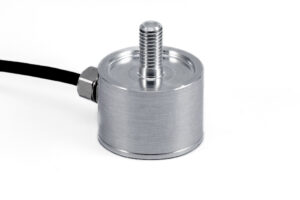
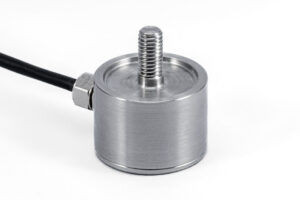
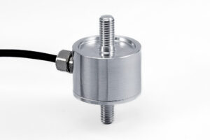
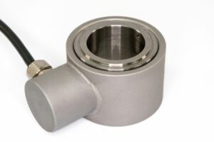
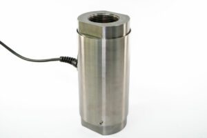
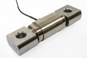
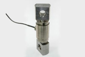
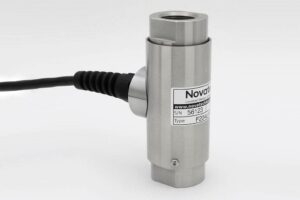
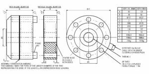
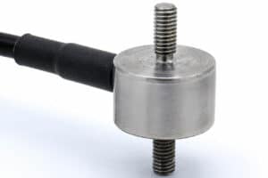
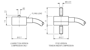
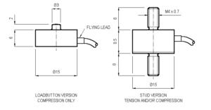
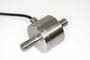
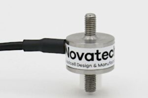
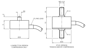
With bi-directional versions there is a small difference between the output signal for compression and tension. All standard bi-directional loadcells are calibrated in both modes and the output for each direction is stated on the test / calibration certificate.
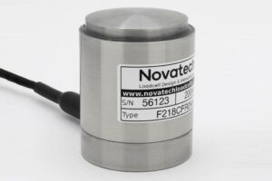
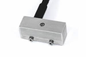
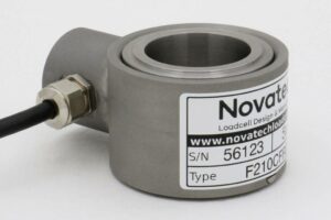
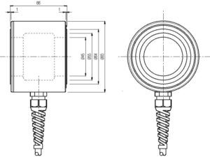
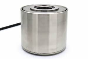
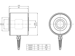
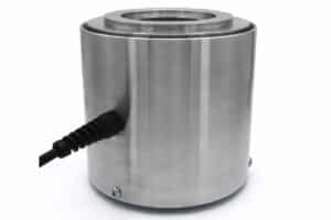
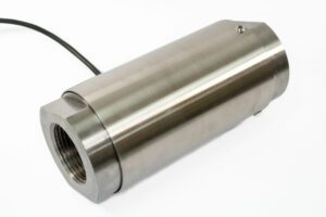
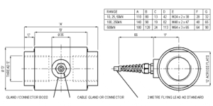
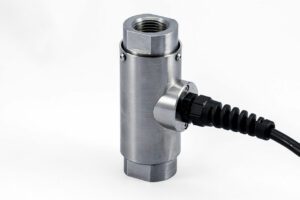
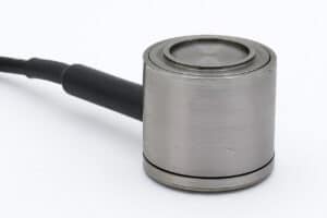
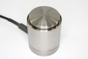
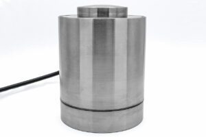
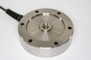
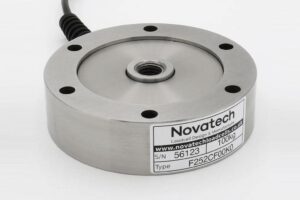
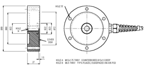
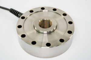
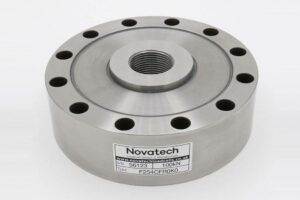
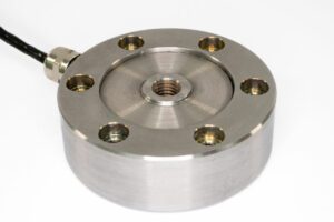
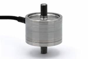
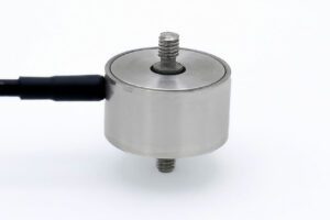
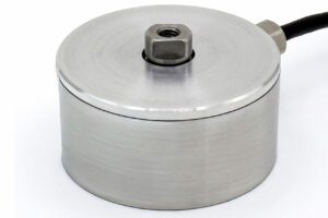
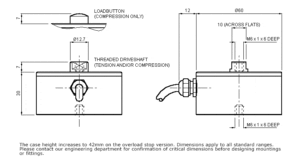
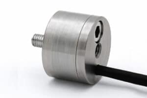
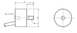
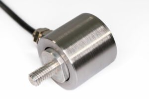
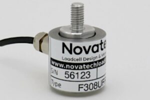
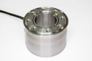
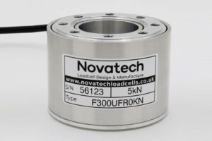
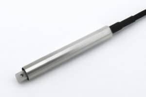
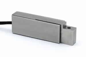
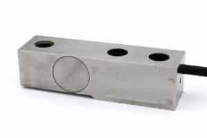
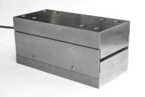
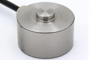
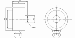
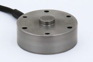
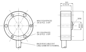
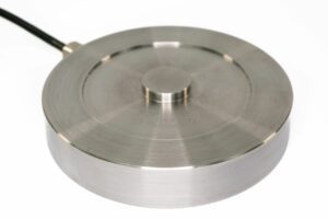
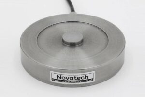
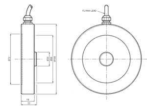
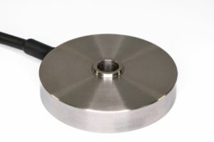
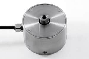
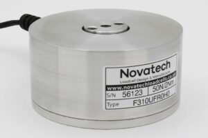
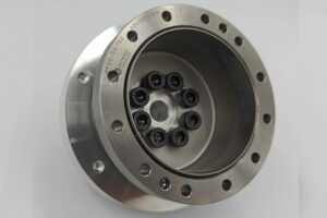
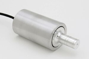
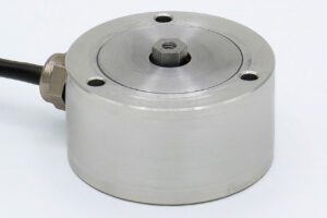
The F252 is ideal for engineering force measurements particularly in applications where there is a limit on the height of the loadcell. It can be used for test machines and a wide range of general industrial applications.
We are happy to design variants of this loadcell to meet your specific requirements. Versions can be manufactured for fully compensated operation up to +250°C. Please consult our engineering department.
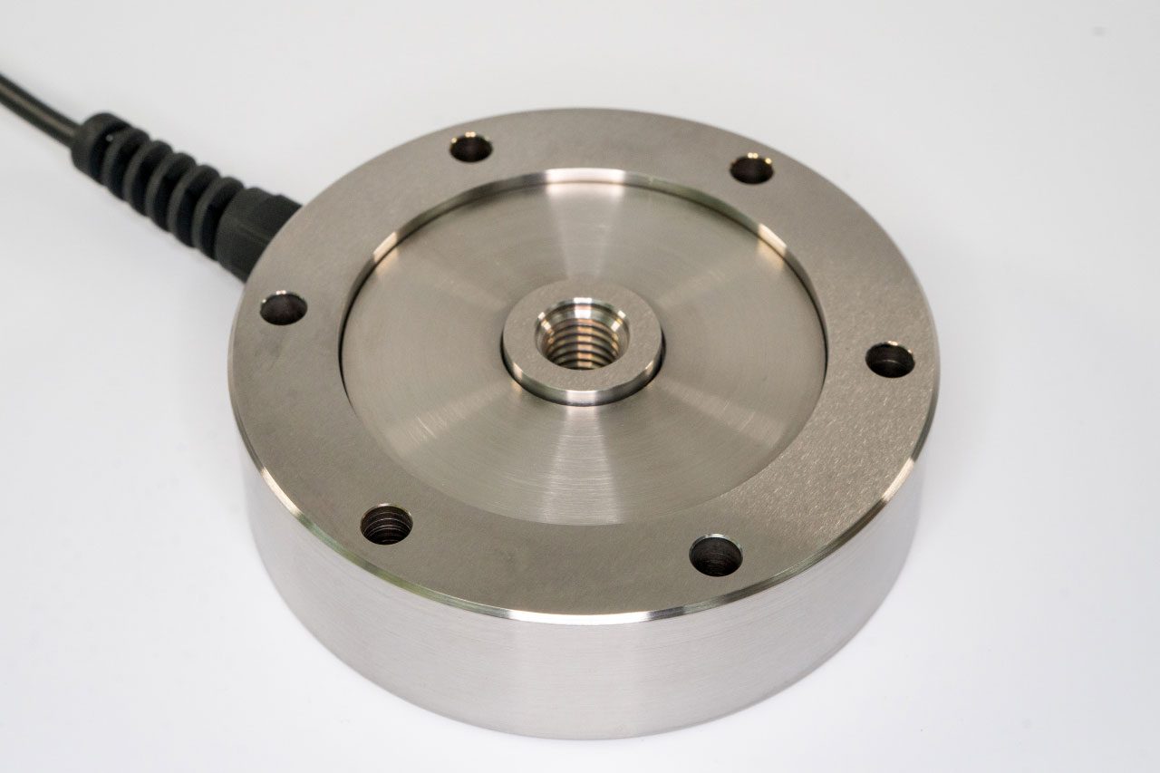
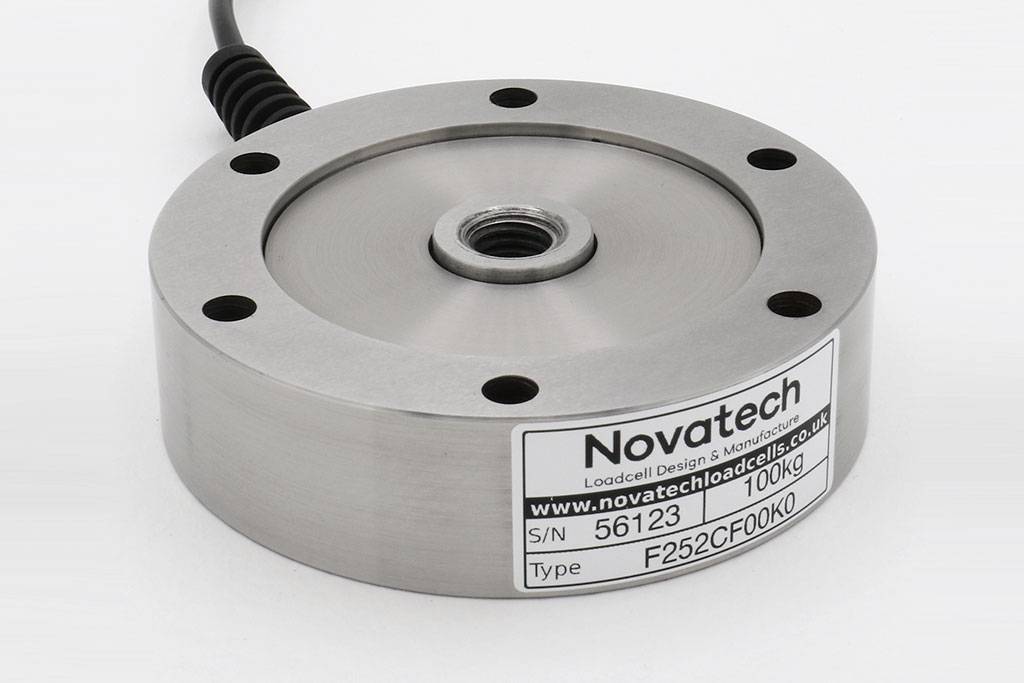
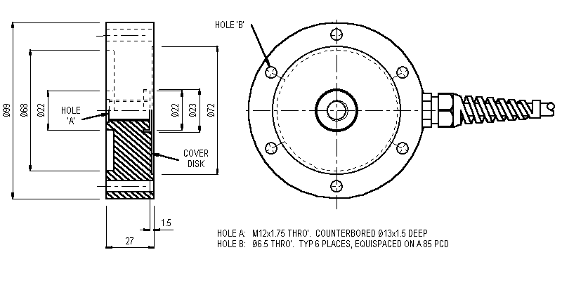
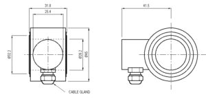
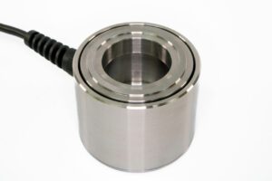
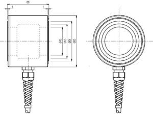
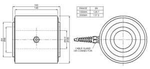
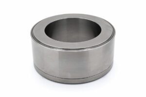
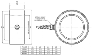
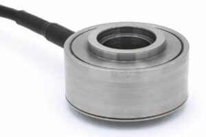
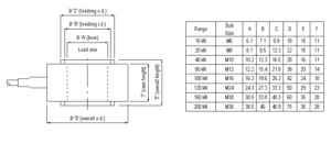
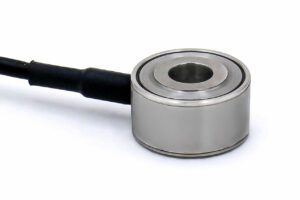
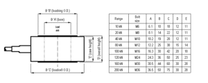
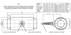
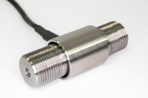
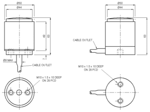
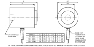
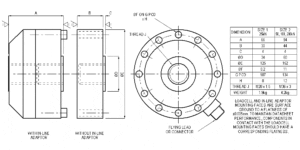
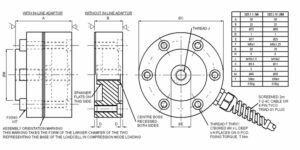
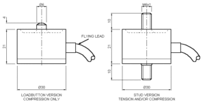
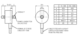
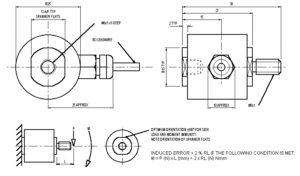
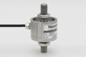
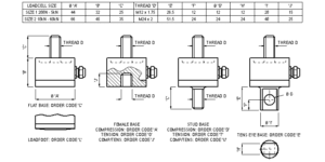
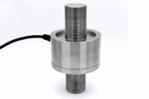
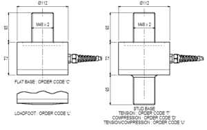
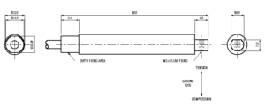
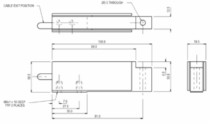
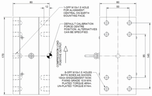
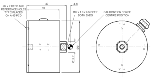
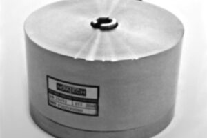
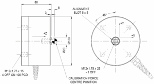
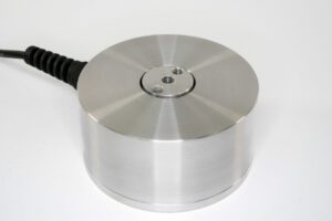
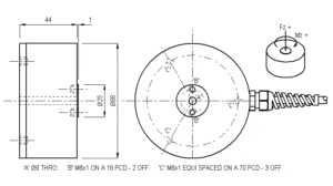
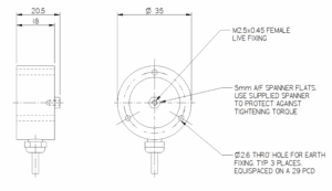
The F252 uses one low-profile axial design that can be supplied for compression, tension, or bi-directional use. Bi-directional units are calibrated in both modes, and every version comes unrationalised or rationalised, giving six standard versions to suit force measurement setups.
About 0.33mm across all standard ranges. Based on the published structural stiffness, from 3.0 x 10⁶ N/m for the 1kN version to 3.0 x 10⁷ N/m for the 10kN version, each F252 deflects roughly the same amount at full rated load, consistent with its listed low-deflection design.
Yes. The F252 accepts a maximum excitation of 20V, although 10V is the recommended level. When sizing your supply, note that bridge resistance is 350Ω for ranges up to 400kgf and 700Ω above 400kgf, so higher-capacity versions draw less current at the same excitation voltage.
| Parameter | Value | Unit |
|---|---|---|
| Non-linearity - Terminal | ±0.1 | % RL |
| Hysteresis | ±0.1 | % RL |
| Creep - 20 minutes | ±0.05 | % AL |
| Repeatability | ±0.02 | % RL |
| Rated output - Nominal | 1.6 | mV/V |
| Rated output - Rationalised | 1.5 | mV/V |
| Rationalisation tolerance (applies to single direction calibrations) | ±0.5 | % RL |
| Zero load output | ±4 | % RL |
| Temperature effect on rated output per °C | ±0.005 | % AL |
| Temperature effect on zero load output per °C | ±0.02 | % RL |
| Temperature range - Compensated | -10 to +50 | °C |
| Temperature range - Safe | -10 to +80 | °C |
| Excitation voltage - Recommended | 10 | V |
| Excitation voltage - Maximum | 20 | V |
| Bridge resistance up to 400kgf | 350 | Ω |
| above 400kgf | 700 | Ω |
| Insulation resistance - Minimum at 50Vdc | 500 | MΩ |
| Overload - Safe | 50 | % RL |
| Overload - Ultimate | 100 | % RL |
| Weight - Nominal (excluding cable) | 840 to 940 | g |
| Code | Description |
|---|---|
| F252CF00K0 | Compression, unrationalised |
| F252TF00K0 | Tension, unrationalised |
| F252UF00K0 | Bi-directional, unrationalised |
| F252CF00KN | Compression, rationalised |
| F252TF00KN | Tension, rationalised |
| F252UF00KN | Bi-directional, rationalised |
| Range (kN) | Stiffness (N/m) |
|---|---|
| 1 | 3.0 x 10⁶ |
| 2 | 6.0 x 10⁶ |
| 4 | 1.2 x 10⁷ |
| 8 | 2.4 x 10⁷ |
| 10 | 3.0 x 10⁷ |