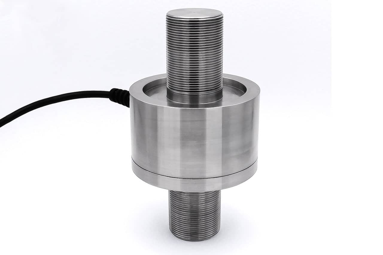
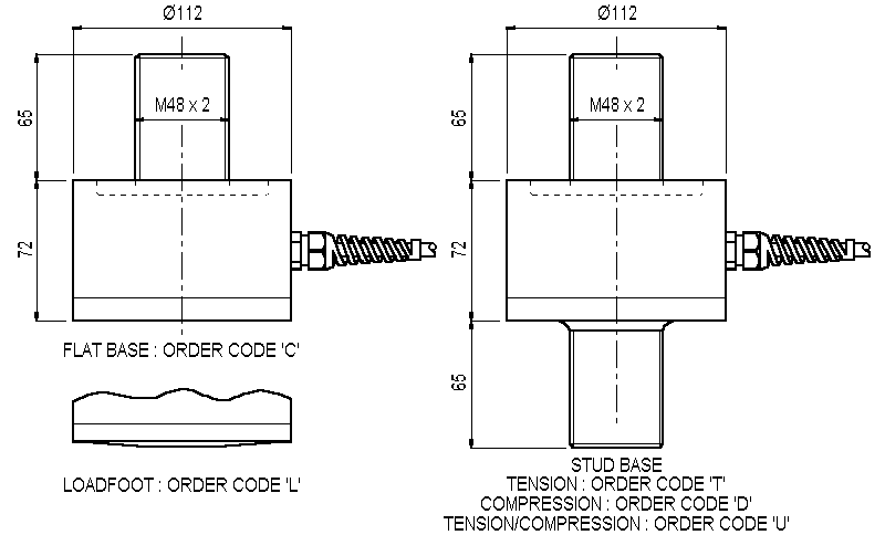
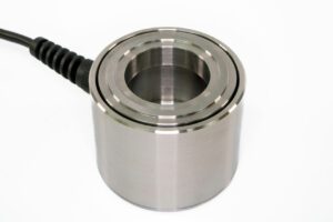
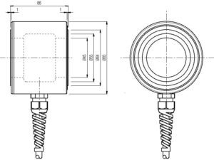
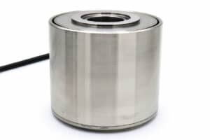
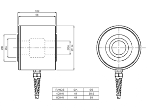
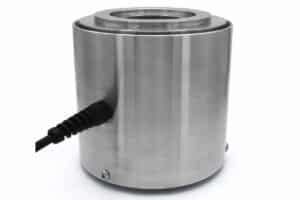
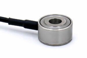
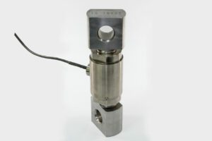
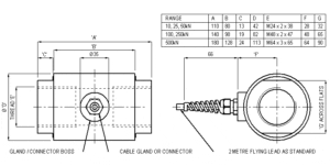
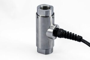
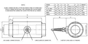
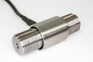
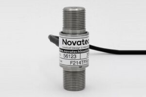
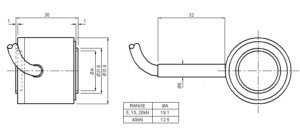
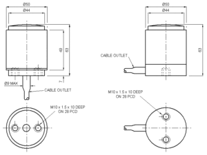
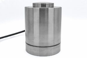
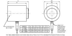
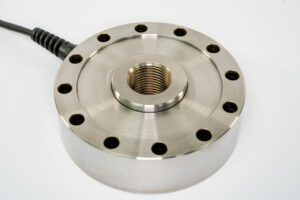
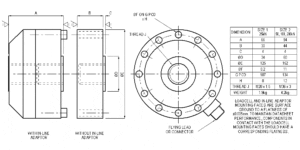
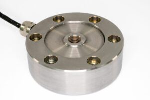
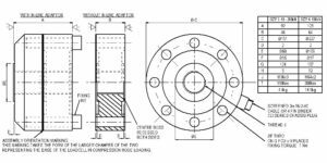
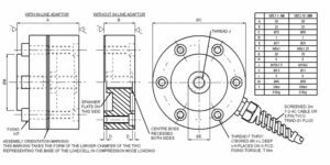
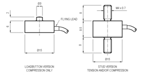
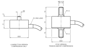
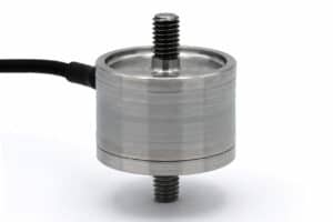
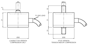
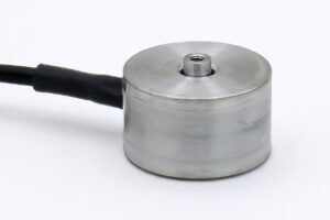
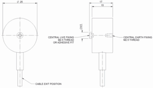
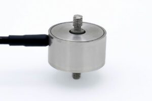
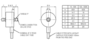
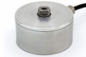
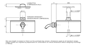
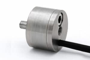
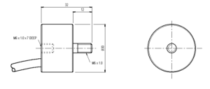
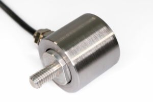
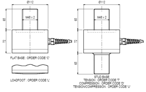
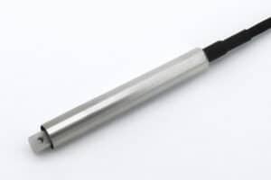
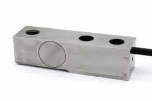
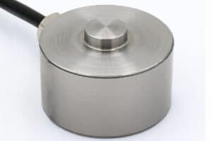
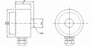
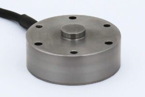
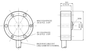
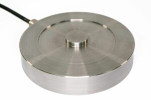
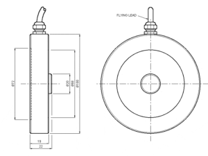
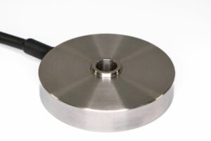
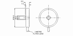
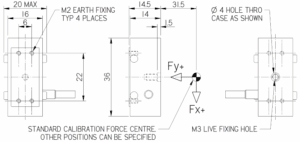
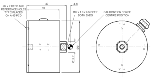
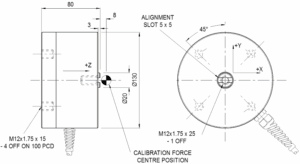
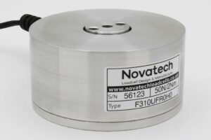
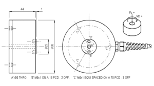
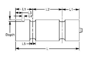
Home » Products » Loadcells » Axial Bending Beam » F257 Axial Compensated Loadcell
The loadcell’s unique strain system compensates for typical force misalignment in force measurement rigs and industrial weighing systems. Its various end fixing options are all inert and easily modified for direct inclusion in mechanical assemblies.
The basic versions of the F257 are all sealed to IP65. If better sealing is required IP67 is available as an option. Integral 4 to 20mA or ±10V output amplifiers can be fitted as an option. Additional information can be found in Engineering Application Sheet E032 and the ICA6H data-sheet.
We are happy to design variants of this loadcell to meet your specific requirements. Versions can be manufactured for operation up to +250°C. Please consult our engineering department.
Parameter | Value | Unit |
---|---|---|
Non-linearity - Terminal | ±0.1 | % RL |
Hysteresis | ±0.1 | % RL |
Creep - 20 minutes | ±0.05 | % AL |
Repeatability | ±0.02 | % RL |
Rated output - Rationalised | 2.0 | mV/V |
Rationalisation tolerance (applies to single direction calibrations) | ±0.1 | % RL |
Zero load output | ±4 | % RL |
Temperature effect on rated output per °C | ±0.002 | % AL |
Temperature effect on zero load output per °C | ±0.005 | % RL |
Temperature range - Compensated | -10 to +50 | °C |
Temperature range - Safe | -10 to +80 | °C |
Excitation voltage - Recommended | 10 | V |
Excitation voltage - Maximum | 20 | V |
Bridge resistance | 700 | Ω |
Insulation resistance - Minimum at 50Vdc | 500 | MΩ |
Inclined load error - concentric at 3° | ±0.25 | % RL |
Overload - Safe | 50 | % RL |
Overload - Ultimate | 100 | % RL |
Sealing - R option | IP65 | |
Sealing - S option | IP67 | |
Weight - Nominal (excluding cable) | 5.5 to 6.5 | kg |
Code | Description |
---|---|
F257CFR0KN | Compression, flat base, IP65 |
F257LFR0KN | Compression, convex base, IP65 |
F257TFR0KN | Tension, stud base, IP65 |
F257DFR0KN | Compression, stud base, IP65 |
F257UFR0KN | Bi-directional, stud base, IP65 |
All F257s are rationalised as standard. Change R to an S for IP67. Integral amplifiers are available with all options. |
Range (kN) | Stiffness (N/m) |
---|---|
80 | 8.0 x 10⁸ |
120 | 1.2 x 10⁹ |
160 | 1.6 x 10⁹ |
240 | 2.4 x 10⁹ |
Title | Type | File |
---|---|---|
Outline drawing of the product. | Outline | Download |
F257CFR0KN All standard ranges | STEP File | Download |
F257LFR0KN All standard ranges | STEP File | Download |
F257-T/D/U-FR0KN All standard ranges | STEP File | Download |
F257 Loadbutton | STEP File | Download |
F257 Top plate | STEP File | Download |
F257 Locknut | STEP File | Download |
F257 Base plate | STEP File | Download |
Drawing of F257 fittings. | Fittings | Download |