| Title | Type | File |
|---|
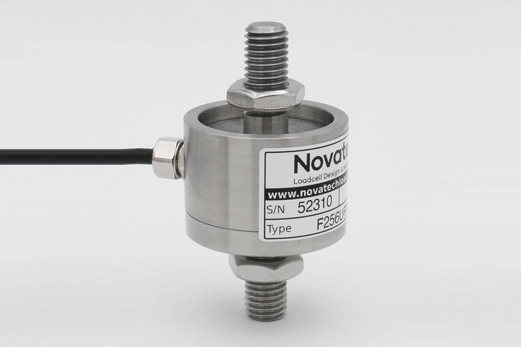
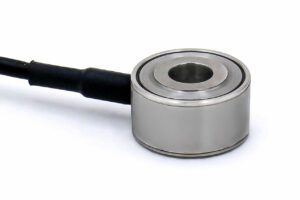
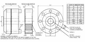
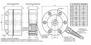
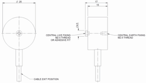
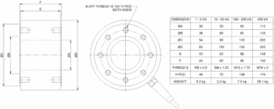
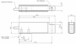
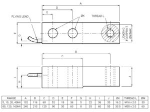
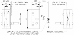
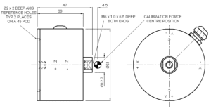
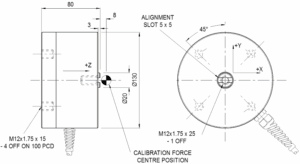
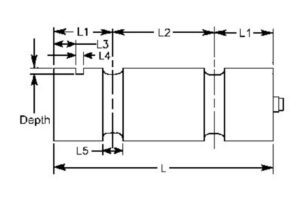
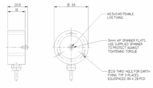
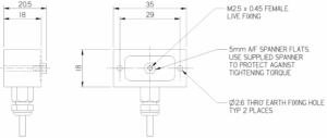
| Outline drawing of the product. | Outline |
Download
|
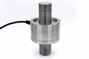
| F256CFR0KN 200N to 5kN (20 to 500kgf) | STEP File |
Download
|
| F256LFR0KN 200N to 5kN (20 to 500kgf) | STEP File |
Download
|
| F256-T/D/U-FR0KN 200N to 5kN (20 to 500kgf) | STEP File |
Download
|
| F256-A/G/J-FR0KN 200N to 5kN (20 to 500kgf) | STEP File |
Download
|
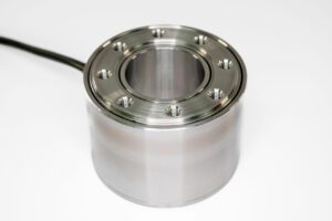
| F256EFR0KN 200N to 5kN (20 to 500kgf) | STEP File |
Download
|
| F256 Loadbutton 200N to 5kN (20 to 500kgf) | STEP File |
Download
|
| F256 Eye attachment 200N to 5kN (20 to 500kgf) | STEP File |
Download
|
| F256 Top plate 200N to 5kN (20 to 500kgf) | STEP File |
Download
|
| F256 Base plate 200N to 5kN (20 to 500kgf) | STEP File |
Download
|
| F256 Locknut 200N to 5kN (20 to 500kgf) | STEP File |
Download
|
| F256 Female attachment 200N to 5kN (20 to 500kgf) | STEP File |
Download
|
| F256CFR0KN 10 to 60kN (1 to 6tonnef) | STEP File |
Download
|
| F256LFR0KN 10 to 60kN (1 to 6tonnef) | STEP File |
Download
|
| F256-T/D/U-FR0KN 10 to 60kN (1 to 6tonnef) | STEP File |
Download
|
| F256-A/G/J-FR0KN 10 to 60kN (1 to 6tonnef) | STEP File |
Download
|
| F256EFR0KN 10 to 60kN (1 to 6tonnef) | STEP File |
Download
|
| F256 Loadbutton 10 to 60kN (1 to 6tonnef) | STEP File |
Download
|
| F256 Eye attachment 10 to 60kN (1 to 6tonnef) | STEP File |
Download
|
| F256 Top plate 10 to 60kN (1 to 6tonnef) | STEP File |
Download
|
| F256 Base plate 10 to 60kN (1 to 6tonnef) | STEP File |
Download
|
| F256 Locknut 10 to 60kN (1 to 6tonnef) | STEP File |
Download
|
| F256 Female attachment 10kN to 60kN (1 to 6tonnef) | STEP File |
Download
|
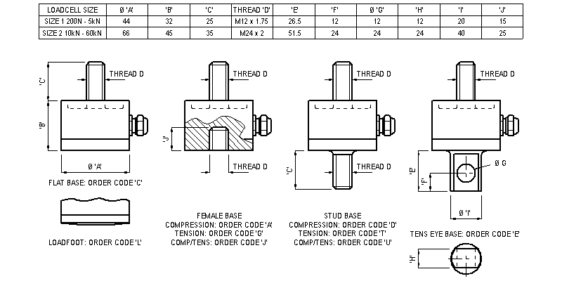
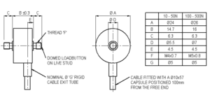
| Drawing of F256 fittings. | Fittings |
Download
|
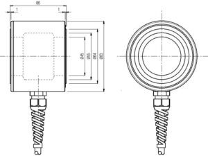
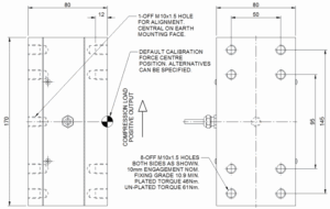
| Drawing of a typical size 1 F256 mounting assembly. (20 to 500kgf) | Mounting |
Download
|
| Drawing of a typical size 2 F256 mounting assembly. (1 to 6tonnef) | Mounting |
Download
|