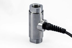
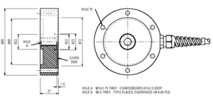
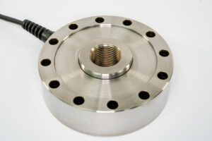
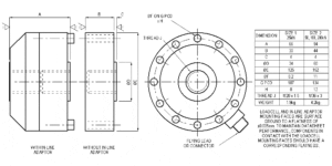
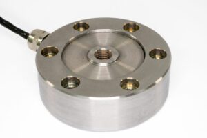
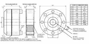
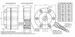
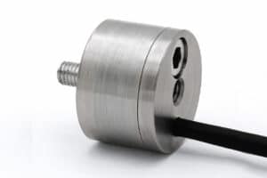
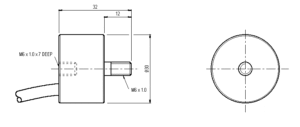
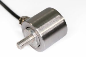
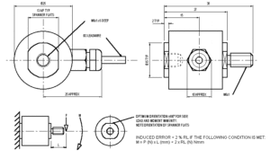
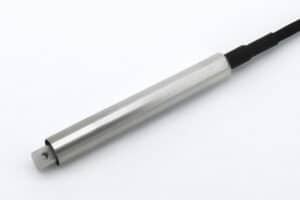
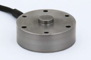
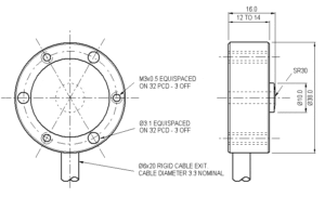
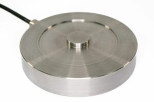
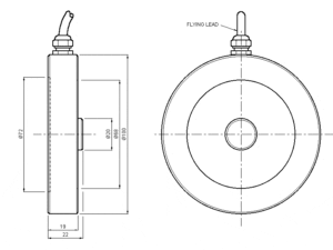
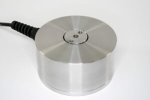
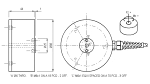
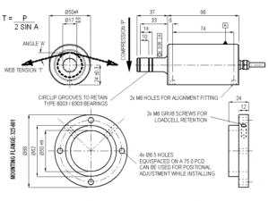
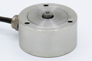
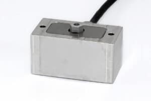
The F254 is designed for high levels of cyclic loading and is readily adapted to series mechanical connection within actuator rods or pistons by using our ‘in-line’ adapter.
The loadcell has good output symmetry between compression and tension operation. All standard bi-directional loadcells are calibrated in both modes. If you require a recessed boss the F318 pancake loadcell may be more suitable. The F318 has standard ranges from 1 to 500kN.
We are happy to design variants of this loadcell to meet your specific requirements. Versions can be manufactured for fully compensated operation up to +250°C. Please consult our engineering department.
| Parameter | Value | Unit |
|---|---|---|
| Non-linearity - Terminal | ±0.1 | % RL |
| Hysteresis | ±0.1 | % RL |
| Creep - 20 minutes | ±0.05 | % AL |
| Repeatability | ±0.02 | % RL |
| Rated output - Nominal | 2.1 | mV/V |
| Rated output - Rationalised | 2 | mV/V |
| Rationalisation tolerance (applies to single direction calibrations) | ±0.5 | % RL |
| Output symmetry | ±0.2 | % AO |
| Fatigue life | 108 | ±RL cycles |
| Zero load output | ±4 | % RL |
| Temperature effect on rated output per °C | ±0.005 | % AL |
| Temperature effect on zero load output per °C | ±0.005 | % RL |
| Temperature range - Compensated | -10 to +50 | °C |
| Temperature range - Safe | -10 to +80 | °C |
| Excitation voltage - Recommended | 10 | V |
| Excitation voltage - Maximum | 20 | V |
| Bridge resistance | 700 | Ω |
| Insulation resistance - Minimum at 50Vdc | 500 | MΩ |
| Fixing bolt torque (bolt grade 8.8) - 25kN range | 25 | Nm |
| - Other ranges | 48 | Nm |
| Overload - Safe | 50 | % RL |
| Overload - Ultimate | 200 | % RL |
| Sealing | IP65 |
| Code | Description |
|---|---|
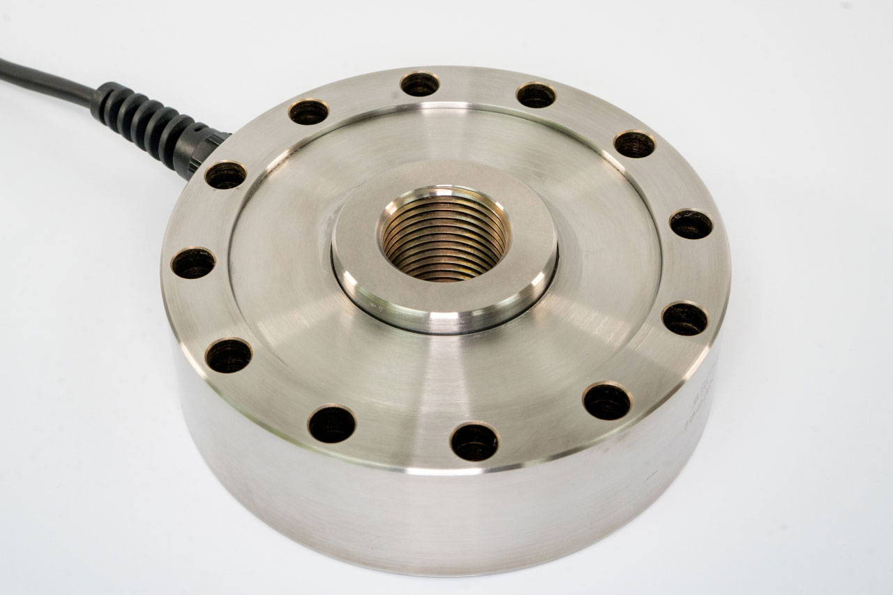
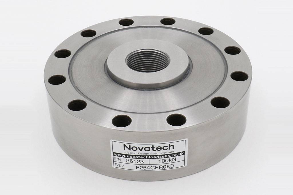
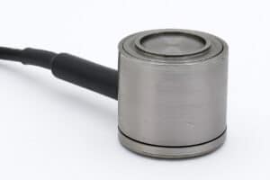
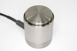
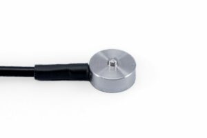
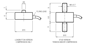
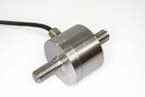
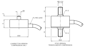
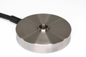
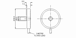
| F254CFR0K0 | Compression, IP65, unrationalised |
| F254TFR0K0 | Tension, IP65, unrationalised |
| F254UFR0K0 | Bi-directional, IP65, unrationalised |
| F254CFR0KN | Compression, IP65, rationalised |
| F254TFR0KN | Tension, IP65, rationalised |
| F254UFR0KN | Bi-directional, IP65, rationalised |
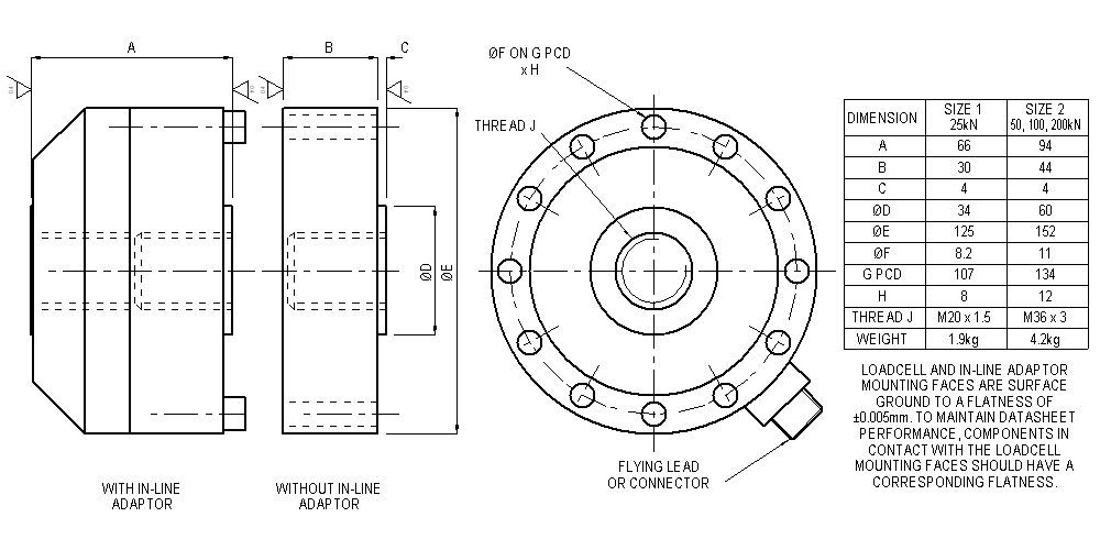
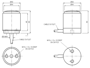
| Change the F to a P for the connector version. |
| Range (kN) | Stiffness (N/m) |
|---|---|
| 25 | 1.3 x 10⁹ |
| 50 | 2.6 x 10⁹ |
| 100 | 1.7 x 10⁹ |
| 200 | 3.4 x 10⁹ |
| Title | Type | File |
|---|---|---|
| Outline drawing of the product. | Outline | Download |
| F254-C/T/U-FR0K0 25kN (2.5tonnef) | STEP File | Download |
| F254-C/T/U-PR0K0 25kN (2.5tonnef) | STEP File | Download |
| F254 In-line adaptor 25kN (2.5tonnef) | STEP File | Download |
| F254 Loadbutton 25kN (2.5tonnef) | STEP File | Download |
| F254 Socket plate 25kN (2.5tonnef) | STEP File | Download |
| F254-C/T/U-FR0K0 50 to 200kN (5 to 20tonnef) | STEP File | Download |
| F254-C/T/U-PR0K0 50 to 200kN (5 to 20tonnef) | STEP File | Download |
| F254 In-line adaptor 50 to 200kN (5 to 20tonnef) | STEP File | Download |
| F254 Loadbutton 50 to 200kN (5 to 20tonnef) | STEP File | Download |
| F254 Socket plate 50 to 200kN (5 to 20tonnef) | STEP File | Download |