With bi-directional versions there is a small difference between the output signal for compression and tension. All standard bi-directional loadcells are calibrated in both modes and the output for each direction is stated on the test / calibration certificate.
The F204 is ideally suited to bi-directional engineering force measurements. They are used extensively within the automotive industry for testing of auto components. Standard rod end bearings are available for this product. If you require better performance than the F204 the F317 may be suitable.
We are happy to design variants of this loadcell to meet your specific requirements. Versions can be manufactured for fully compensated operation up to +250°C. Please consult our engineering department.
Parameter | Value | Unit |
---|---|---|
Non-linearity - Terminal | ±0.2 (10 to 100kN) / ±0.5 (250 to 500kN) | % RL |
Hysteresis | ±0.2 (10 to 100kN) / ±0.5 (250 to 500kN) | % RL |
Creep - 20 minutes | ±0.05 | % AL |
Repeatability | ±0.02 (10 to 100kN) / ±0.03 (250 to 500kN) | % RL |
Rated output - Nominal | 1.2 (10 to 100kN) / 1.2 (250 to 500kN) | mV/V |
Rated output - Rationalised | 1.0 (10 to 100kN) / 1.0 (250 to 500kN) | mV/V |
Rationalisation tolerance (applies to single direction calibrations) | ±0.5 (10 to 100kN) / ±0.5 (250 to 500kN) | % RL |
Zero load output | ±4 (10 to 100kN) / ±4 (250 to 500kN) | % RL |
Temperature effect on rated output per °C | ±0.005 (10 to 100kN) / ±0.005 (250 to 500kN) | % AL |
Temperature effect on zero load output per °C | ±0.03 (10 to 100kN) / ±0.03 (250 to 500kN) | % RL |
Temperature range - Compensated | -10 to +50 (10 to 100kN) / -10 to +50 (250 to 500kN) | °C |
Temperature range - Safe | -10 to +80 (10 to 100kN) / -10 to +80 (250 to 500kN) | °C |
Excitation voltage - Recommended | 10 (10 to 100kN) / 10 (250 to 500kN) | V |
Excitation voltage - Maximum | 20 (10 to 100kN) / 20 (250 to 500kN) | V |
Bridge resistance | 700 (10 to 100kN) / 700 (250 to 500kN) | Ω |
Insulation resistance - Minimum at 50Vdc | 500 (10 to 100kN) / 500 (250 to 500kN) | MΩ |
Overload - Safe | 50 (10 to 100kN) / 50 (250 to 500kN) | % RL |
Overload - Ultimate | 200 (10 to 100kN) / 200 (250 to 500kN) | % RL |
Sealing | IP65 (10 to 100kN) / IP65 (250 to 500kN) | |
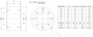
Weight - Nominal (excluding cable) | 0.7 (10 to 50kN) / 3.2 (100 - 250kN) / 7.8 (500kN) | kg |
Code | Description |
---|---|
F204CFR0K0 | Compression, IP65, unrationalised |
F204TFR0K0 | Tension, IP65, unrationalised |
F204UFR0K0 | Bi-directional, IP65, unrationalised |
F204CFR0KN | Compression, IP65, rationalised |
F204TFR0KN | Tension, IP65, rationalised |
F204UFR0KN | Bi-directional, IP65, rationalised |
Range (kN) | Stiffness (N/m) |
---|---|
10 | 2.8 x 10⁸ |
25 | 7.0 x 10⁸ |
50 | 1.4 x 10⁹ |
100 | 2.7 x 10⁹ |
250 | 6.8 x 10⁹ |
500 | 1.4 x 10¹⁰ |
Title | Type | File |
---|---|---|
Outline drawing of the product. | Outline | Download |
F204-C/T/U-FR0K0 10 to 50kN (1 to 5tonnef) | STEP File | Download |
F204-C/T/U-FR0K0 100 to 250kN (10 to 25tonnef) | STEP File | Download |
F204-C/T/U-FR0K0 500kN (50tonnef) | STEP File | Download |
F204-C/T/U-PR0K0 10 to 50kN (1 to 5tonnef) | STEP File | Download |
F204-C/T/U-PR0K0 100 to 250kN (10 to 25tonnef) | STEP File | Download |
F204-C/T/U-PR0K0 500kN (50tonnef) | STEP File | Download |