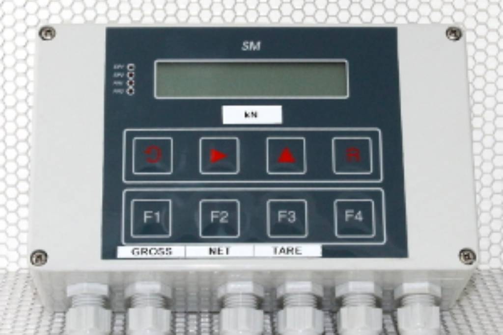
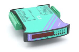
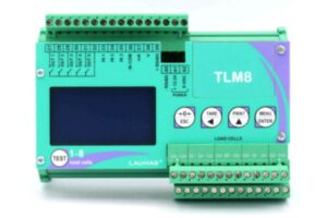
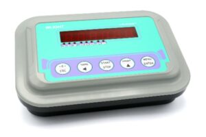
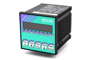
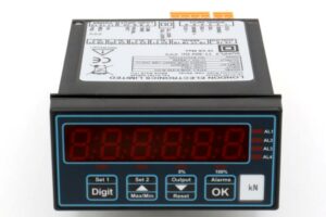
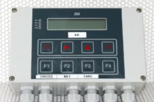
This panel or wall mounting loadmeter is designed for use with strain gauge loadcells.
It is a self contained instrument that combines ease of use with a wide range of features including analogue output as standard and options to add trip points and serial communications.
The 4 to 20mA and 0 to 10V outputs can both be used at the same time but only one can be accurately calibrated. See the SMW specification for more information. The normal set-up is to calibrate the 4 to 20mA output accurately unless special instructions are given with an order. The analogue output is uni-polar so if a bi-directional loadcell is used the only way to scale the amplifier is to set the mid-point of the analogue output equal to zero load. This will be 12mA or 5V.
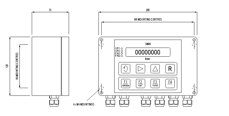
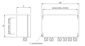
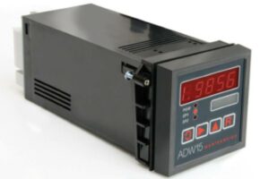
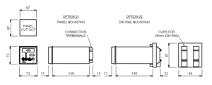
All set up functions are via the IP65 sealed keypad using a simple menu system. A version is available for panel mounting in control enclosures, the main circuit board being DIN rail mounted within the enclosure. The eight digit LCD display is also available with back lighting.
An RS232/RS485 serial communications option is available for single links or multi-drop applications of up to 25 weigh stations.
If the SMW is supplied with a loadcell it will normally be calibrated to read the loadcell output in the same force units as the loadcell calibration. A traceable system certificate will be supplied for the loadmeter and loadcell combination.
It is a self contained instrument that combines ease of use with a wide range of features including analogue output as standard and options to add trip points and serial communications.
The 4 to 20mA and 0 to 10V outputs can both be used at the same time but only one can be accurately calibrated. See the SMW specification for more information. The normal set-up is to calibrate the 4 to 20mA output accurately unless special instructions are given with an order. The analogue output is uni-polar so if a bi-directional loadcell is used the only way to scale the amplifier is to set the mid-point of the analogue output equal to zero load. This will be 12mA or 5V.
All set up functions are via the IP65 sealed keypad using a simple menu system. A version is available for panel mounting in control enclosures, the main circuit board being DIN rail mounted within the enclosure. The eight digit LCD display is also available with back lighting.
An RS232/RS485 serial communications option is available for single links or multi-drop applications of up to 25 weigh stations.
If the SMW is supplied with a loadcell it will normally be calibrated to read the loadcell output in the same force units as the loadcell calibration. A traceable system certificate will be supplied for the loadmeter and loadcell combination.
Specification
Parameter
Value
Unit
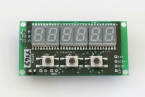
Display
4½ digit LCD display maximum display of 199990
Display update rate
0.1 to 25.5 seconds
Calibration
Automatic digital by use of keypad and known weights
Sensitivity
0.5 to 200mV/V
Accuracy
90 days ±0.08% of reading ±0.05% of FSD typical
Drift - zero
0.002% full range / °C typical at 2.5mV/V
Drift - span
0.005% reading / °C
Analogue output
4 to 20mA, loop resistance <1k0Ω - typical accuracy 0.15% of range. 0 to 10V, load resistance >5k0Ω - accurate to within 2% of 4 to 20mA
Settling time
0.35 secs to 1% of step change
Loadcell supply
9.6Vdc at 150mA (4 x 350W loadcells), with remote sensing
Operating temperature
-10°C to +50°C
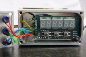
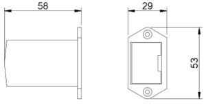
Case sealing
IP65 for /C versions
Supply requirements
115/230Vac (LS1) or 9-32Vdc (LS3), power 10 Watts
Order Codes
Code
Description
SMW/C-LS1
Basic loadmeter in an IP65 case.
SMW/C-/BL-LS1
Basic loadmeter in an IP65 case with a backlit display.
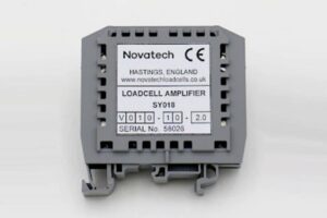
SMW/D-LS1
DIN rail mounted loadmeter with a separate display.
SMW/D/BL-LS1
DIN rail mounted loadmeter with a separate back lit display.
For 9-32Vdc powered versions change LS1 to LS3. Other options - add the code to the basic ordering code.
-LC3
RS232/RS485 serial communications. This can be configured for use with a printer or a computer. ASCII or fast format protocols can be selected.
-LR1
2 set points. Each set point has a SPCO relay contact rated at 5A 240Vac, resistive load
Notes
Supplied with an operators manual giving full details of the programmable parameters. The parameters are stored in non-volatile memory.
These instrumentation products comply with the requirements of the European EMC directive.